skip to content
Toby Lunt

A new mast

/ 9 min read

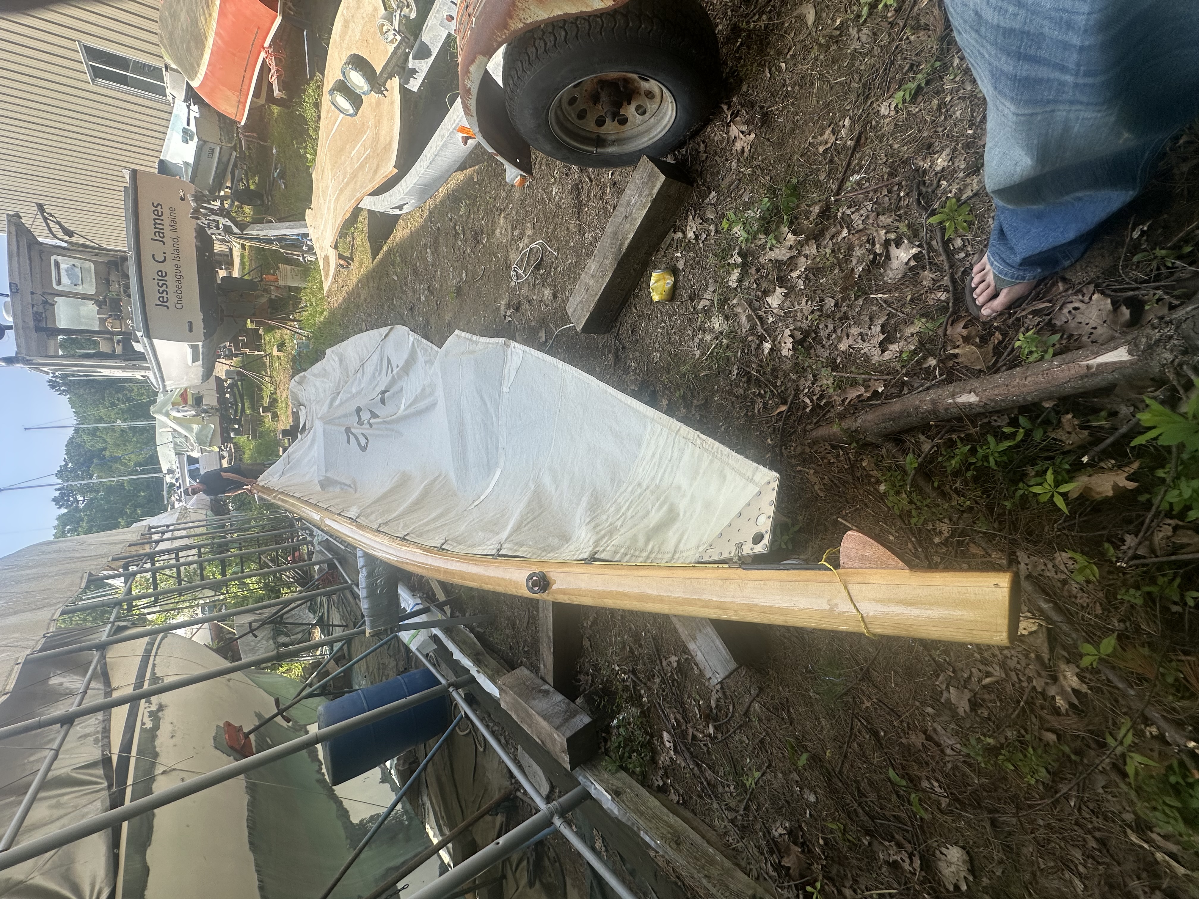
Ariadne is a 22 Square Meter — a Swedish class of racing sailboat designed in the 1920s and ’30s that most people outside Scandinavia have never heard of. The boats are lovely: long overhangs, bright mahogany, an elegant rig, and proportions that make them look fast standing still. They were built to a box rule that governed sail area and a handful of hull dimensions but left the builder considerable freedom in how to get there, which means no two are quite alike.

Page from a book showing Swedish square-meter rule yachts racing
Swedish square-meter rule boats racing — Rival (S 10) and Boja sailing upwind under full sail. Ariadne is this type of boat: long overhangs, a tall fractional rig, and lines that haven't aged a day.
Ariadne hauled out in a boatyard with her old mast stepped
Ariadne hauled out around 2005 with her old mast standing. Notice the bend at the tip baked into the spar. She's been out of the water for a long time now, but the rig seemed mostly intact when we started this project...
Looking up the old mast from the spreaders
Looking up the old mast. They don't make 'em like this anymore. (They make them better)

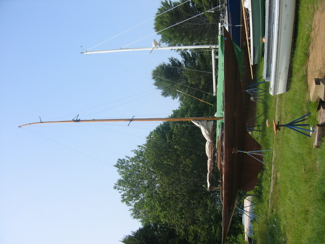
When we began Ariadne’s restoration, we assumed the mast would be one of the easier chapters. The spar was original — a hollow spruce stick that had been aloft for the better part of a century. It had some cracks, some old modifications, and a lot of character. Our plan was to stabilize the damage, replace the worst section at the mast butt, and go sailing. That is unfortunately not how things played out.

The old spar

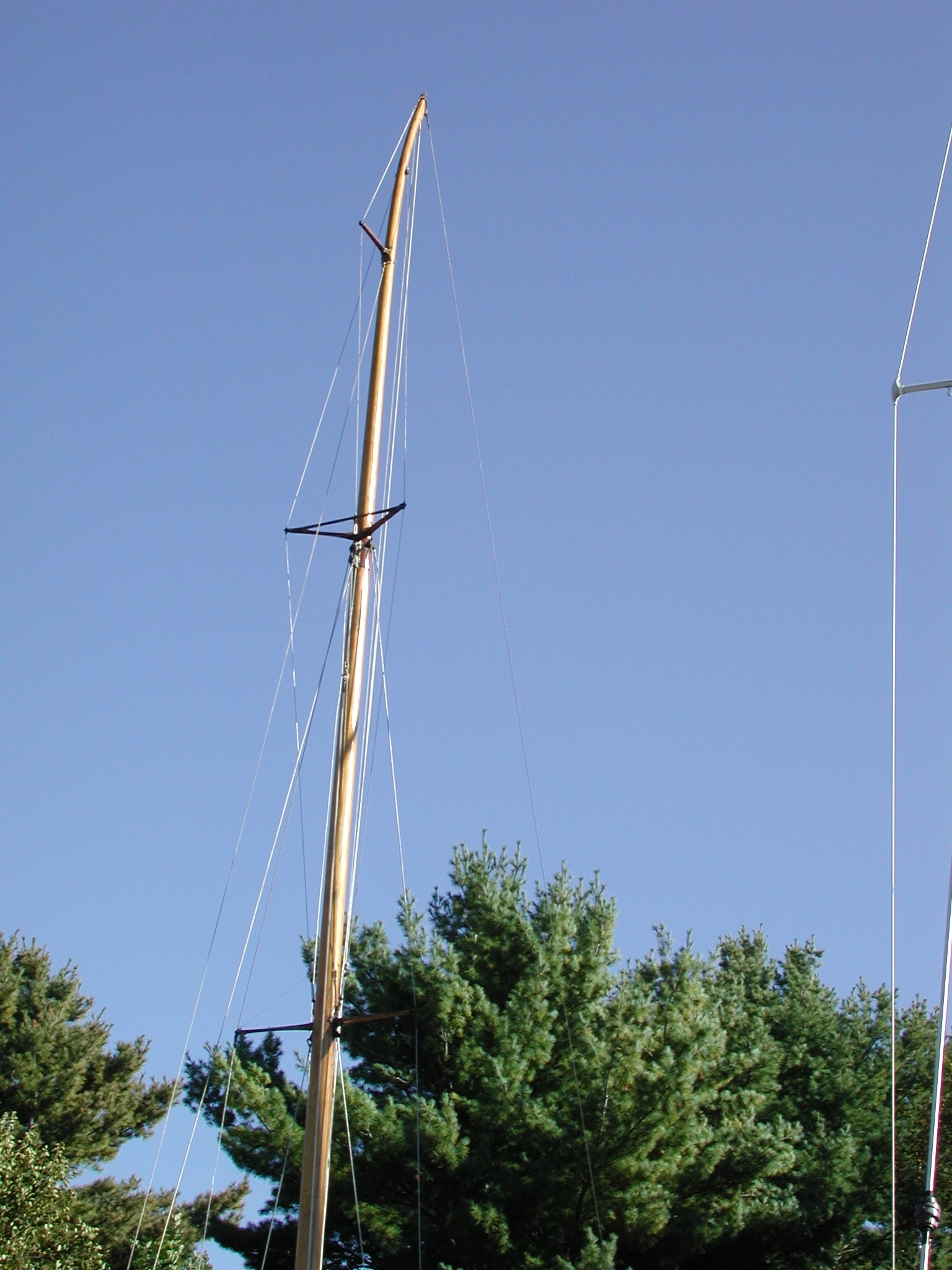
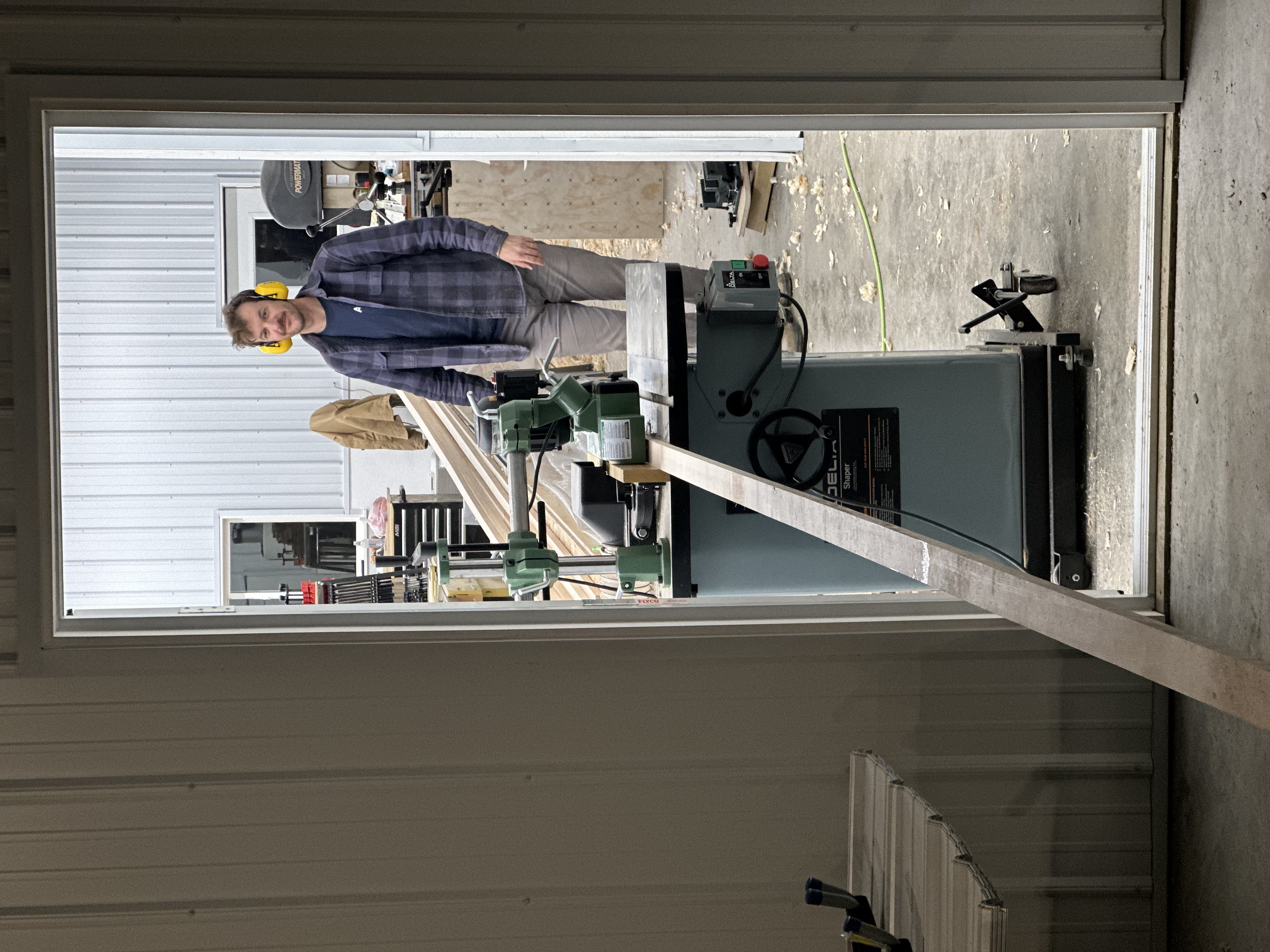
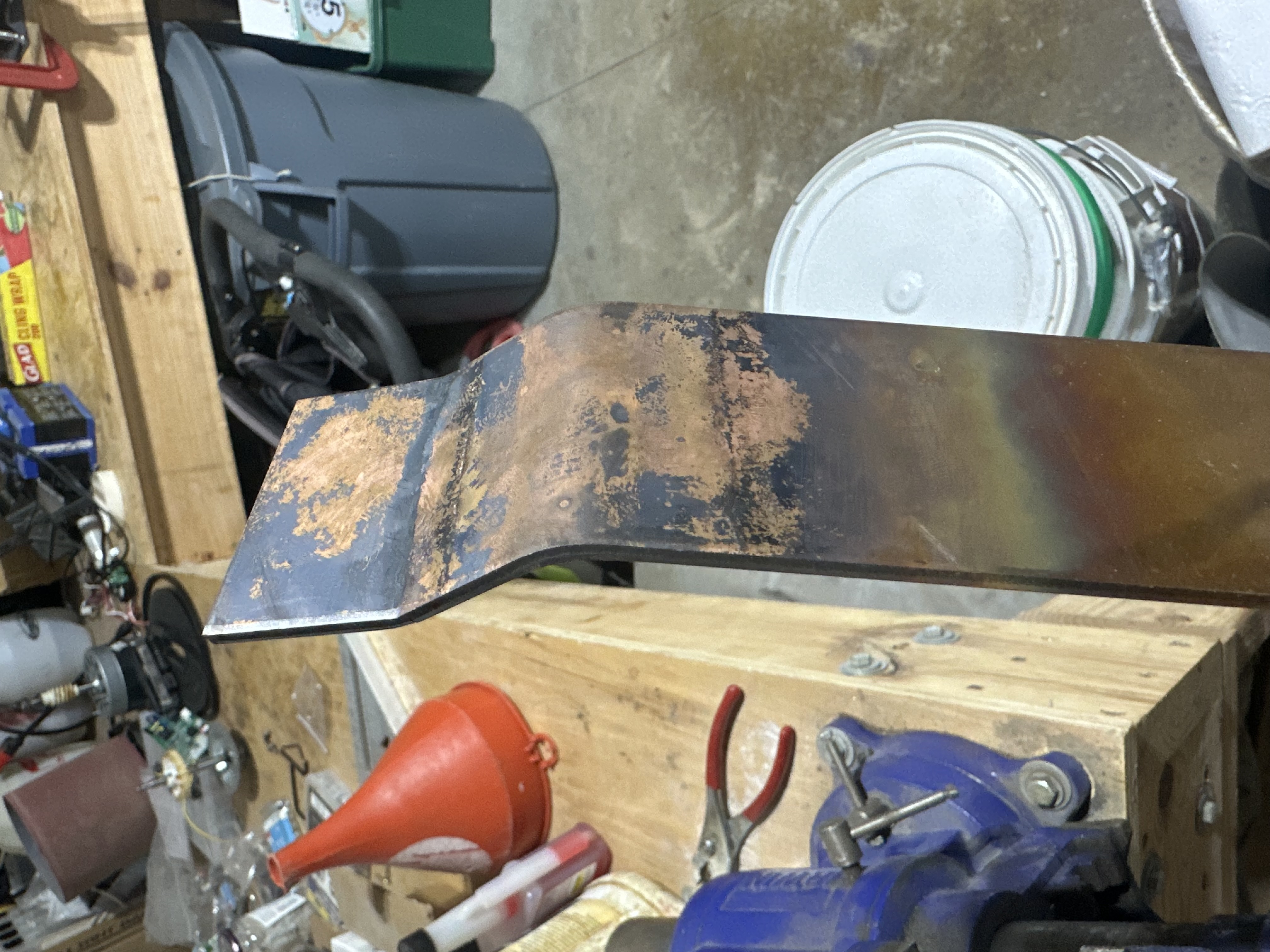
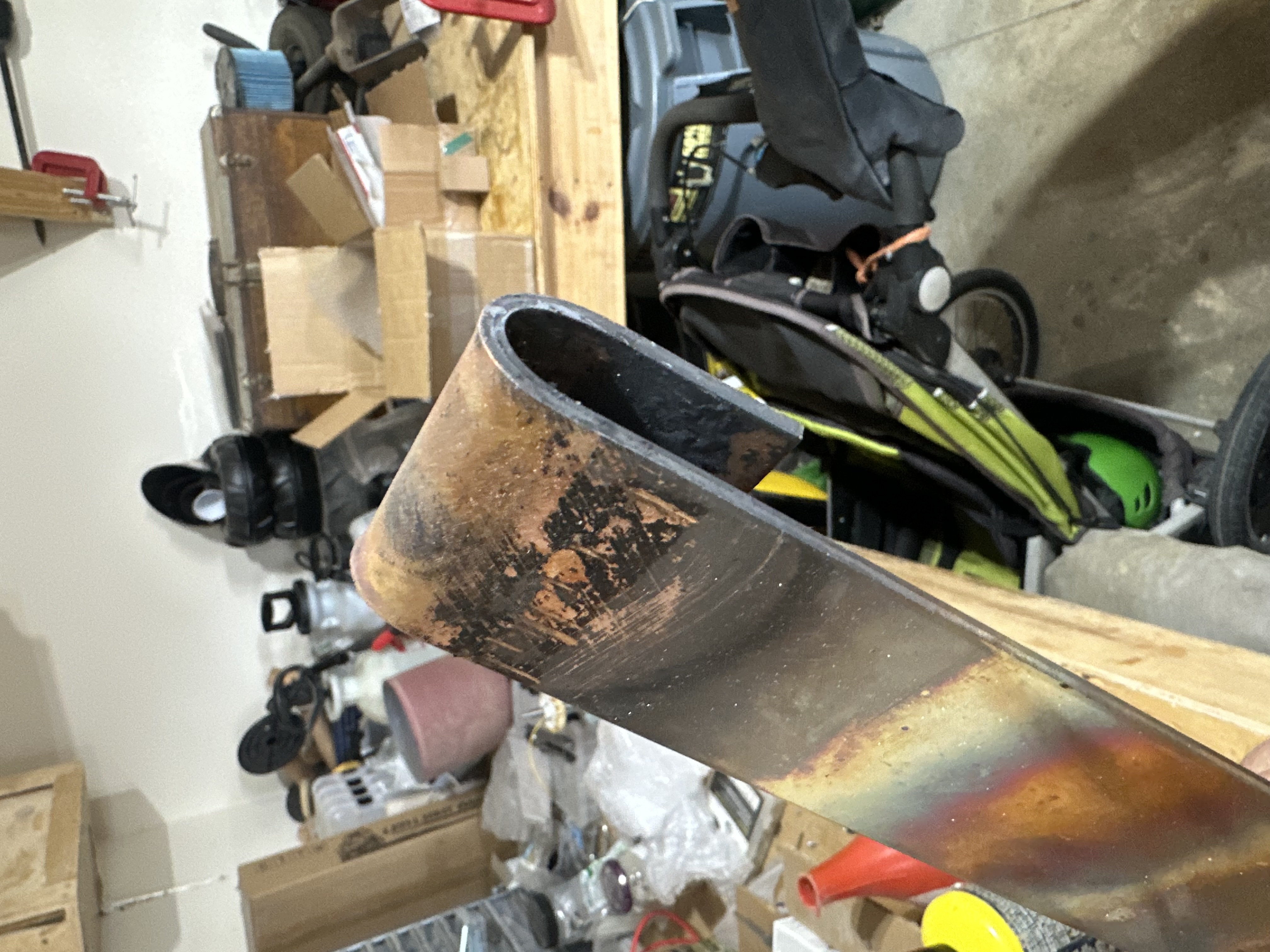
For the first five or so years of the restoration, the mast hung up on the wall of a boatyard shed. So when we were finally ready to think about rigging, the first step was a thorough rig inspection. We pulled the mast out of storage, set it on sawhorses, and started looking. It was worse than we remembered.

Close-up of old mast hardware showing wear and deterioration
Representative shot of the original hardware. Swaged wire terminals, custom chafe guards made from electrical tape, seized sheaves, structural layers of varnish. What could go wrong?
Old mast showing sail track and severe splitting
The sail track runs the length of the aft face. Beneath it, the wood has a gnarly crack — the track fastenings created a weakness and the mast broke across the grain.
Old mast showing bronze fitting and longitudinal split
A shroud termination sheave with a split along the grain running past it. This was an original glue line that opened up.
Close-up of the old mast's splintered butt end
Mast butt with structural electrical tape. The splintering was remarkable and irretrievable.
The heel end of the old mast
The butt end with the electrical tape removed. Seems legit.

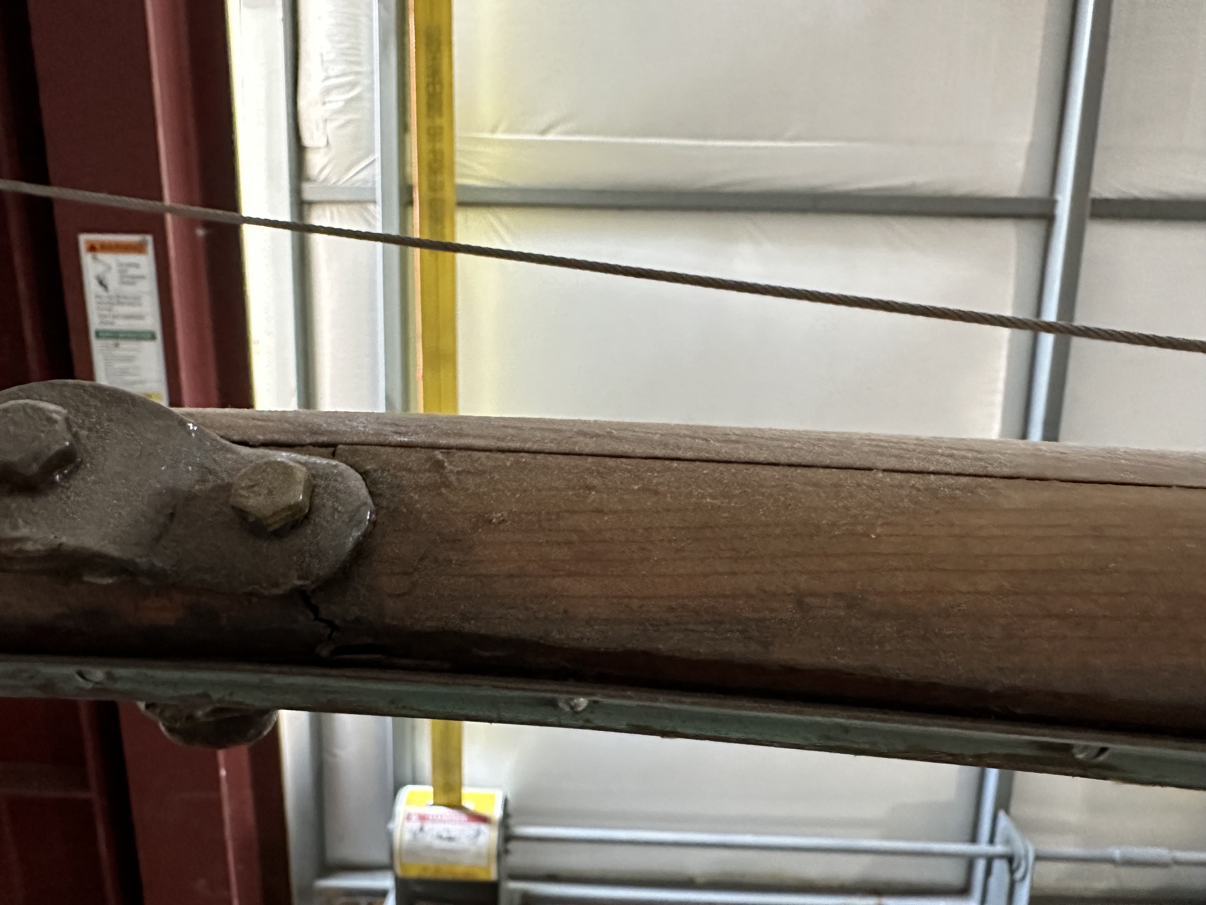
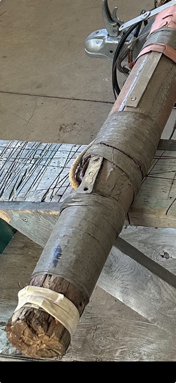
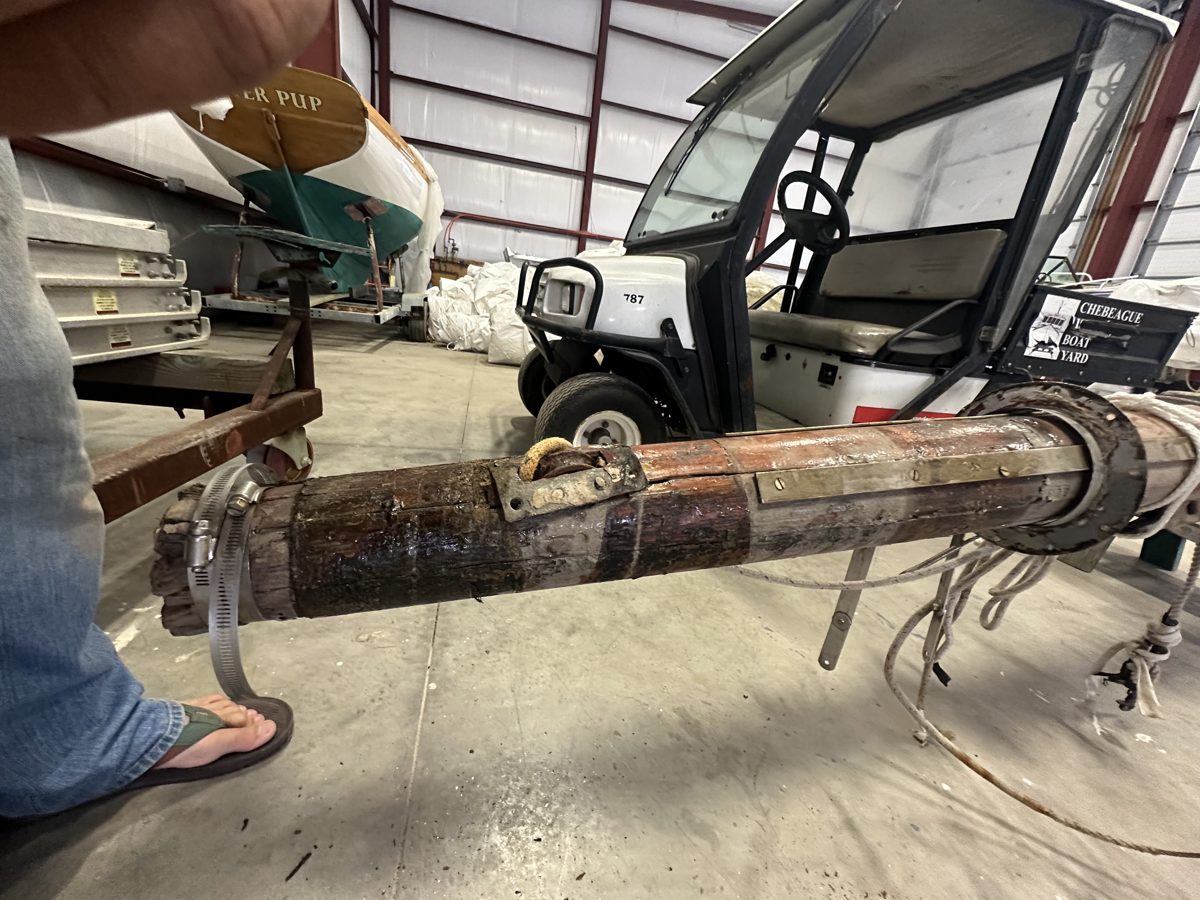
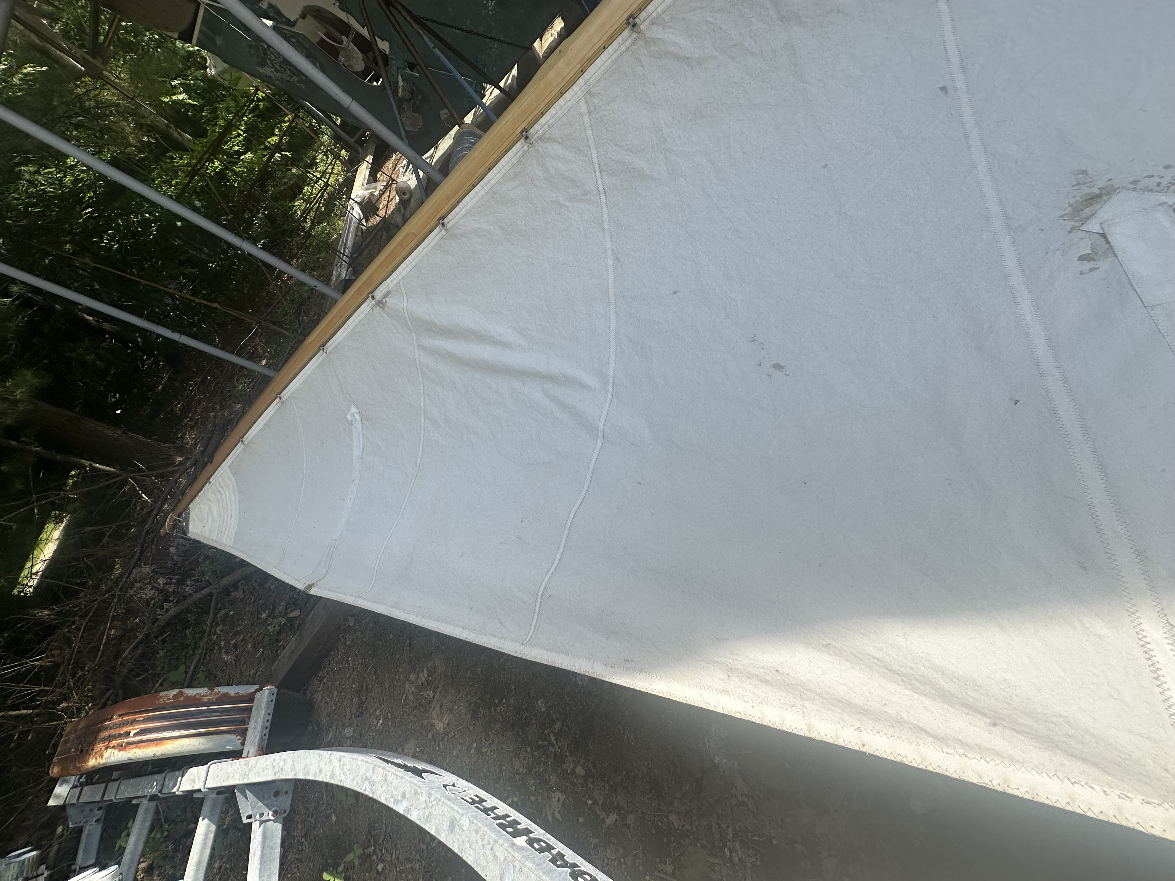
Splintered down low, cracked aloft, and with failing hardware in between!

Time for a new mast

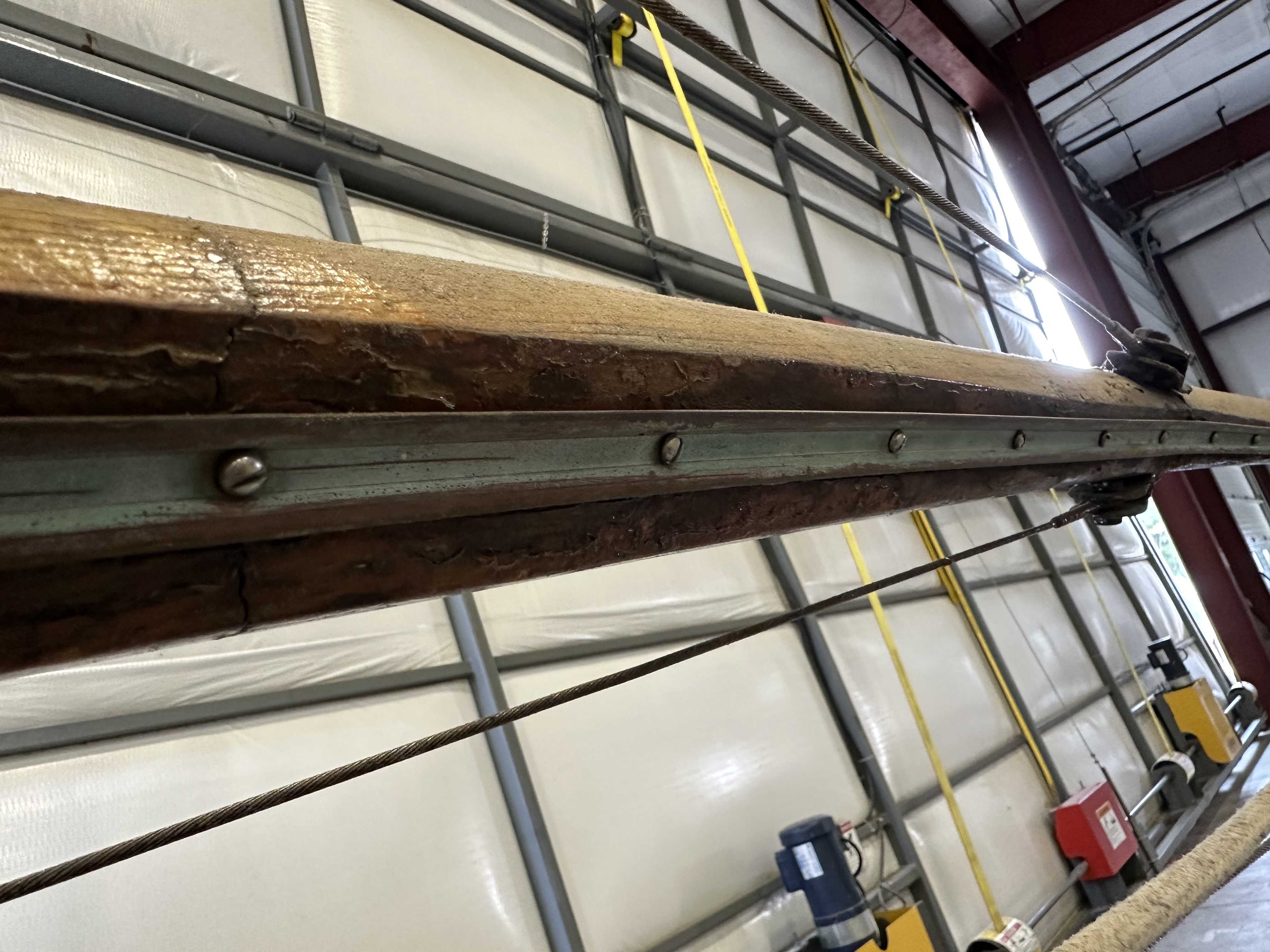
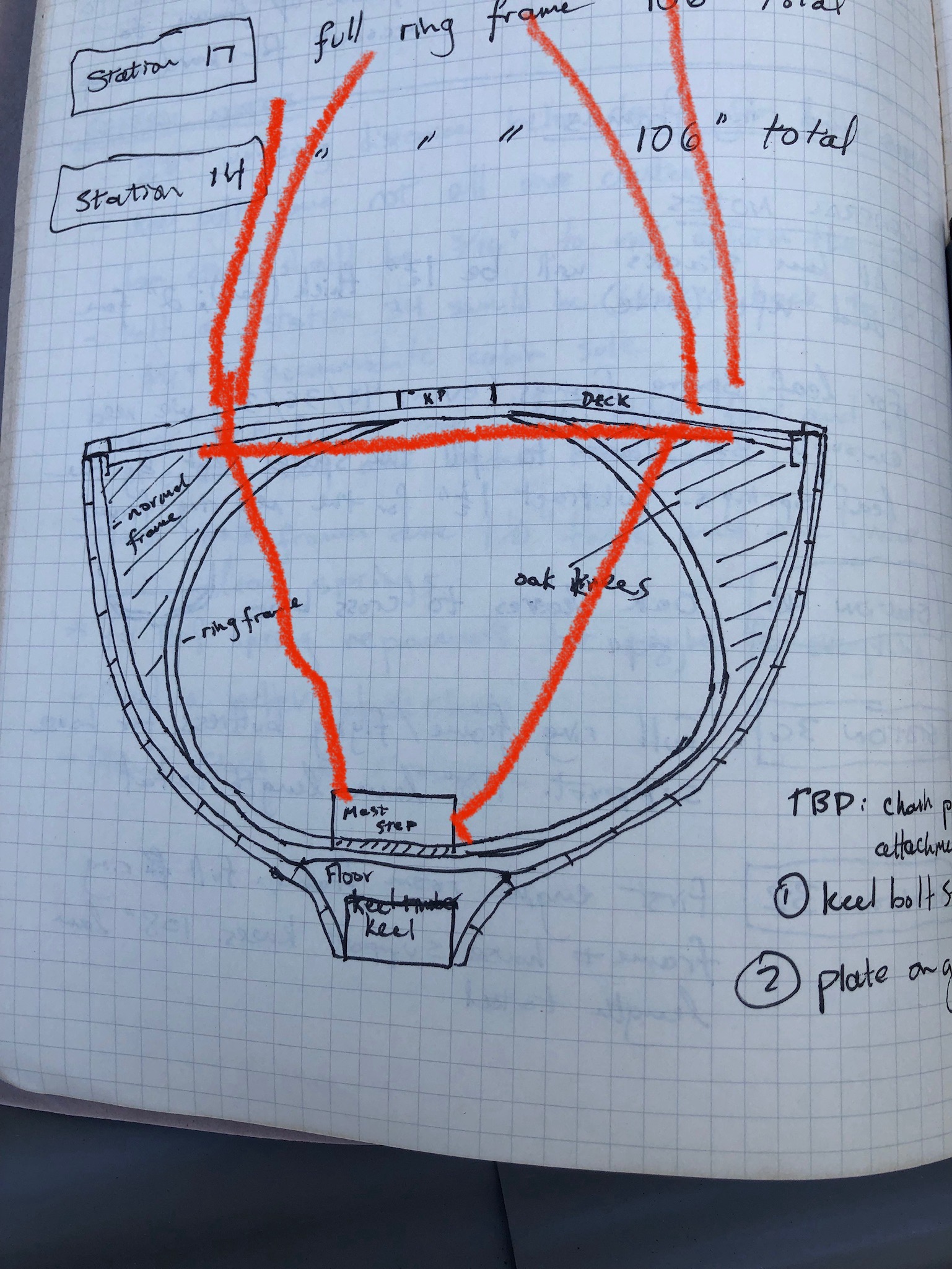
Before we could build a replacement, we needed to pull an array of important measurements from what we were replacing. We recorded every identifiable dimension of the old spar — cross-sections at regular intervals, locations of every fitting and feature, the taper profile, the curve at the mast tip, the flat for the sail track.

Notebook page listing every feature along the mast
The detailed index — every feature from tip to heel: backstay, sail track, shroud bands, forestay, spreaders, halyard exits, wood cleats, all with their distances from tip and the corresponding cross-section dimensions.
Notebook page with jumper strut and spreader details
Spreader geometry and dimensions, and offsets for the curve baked into the mast tip. The jumper strut was added to the old mast at some point — it wasn't original to the Swedish build - but the Marconi triangle was original.

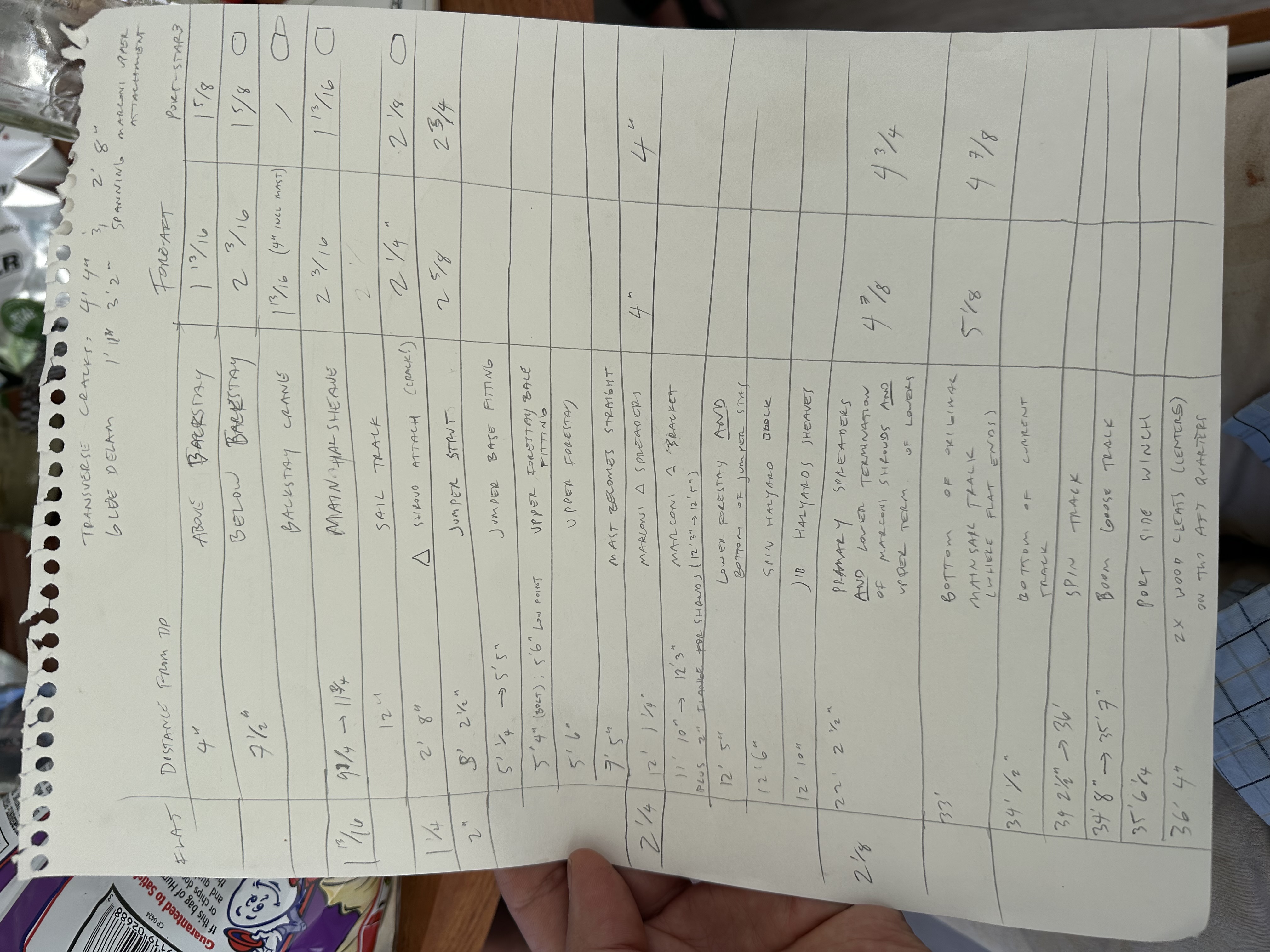
Between these detailed registration points from the old spar and the new rig design, we had enough information to put together a sufficiently detailed construction plan for the replacement mast.

Engineering

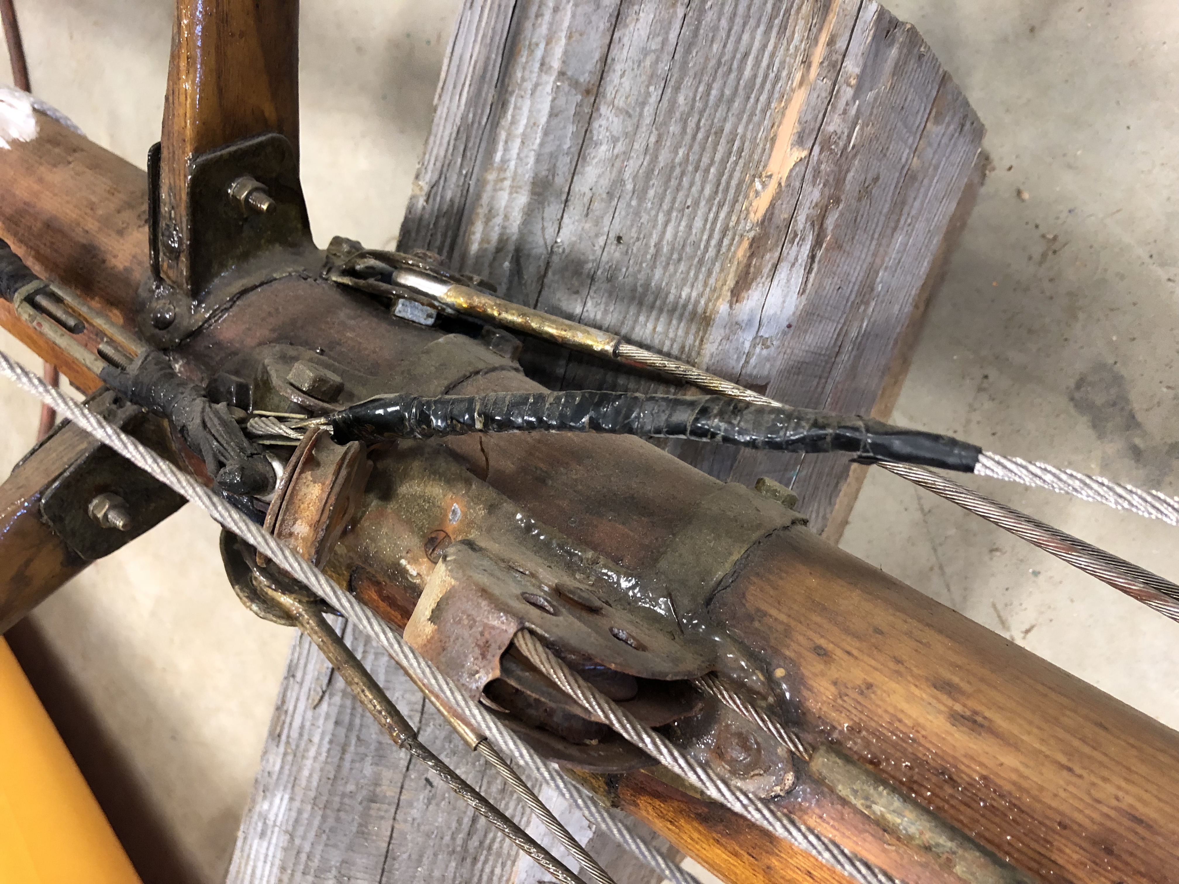
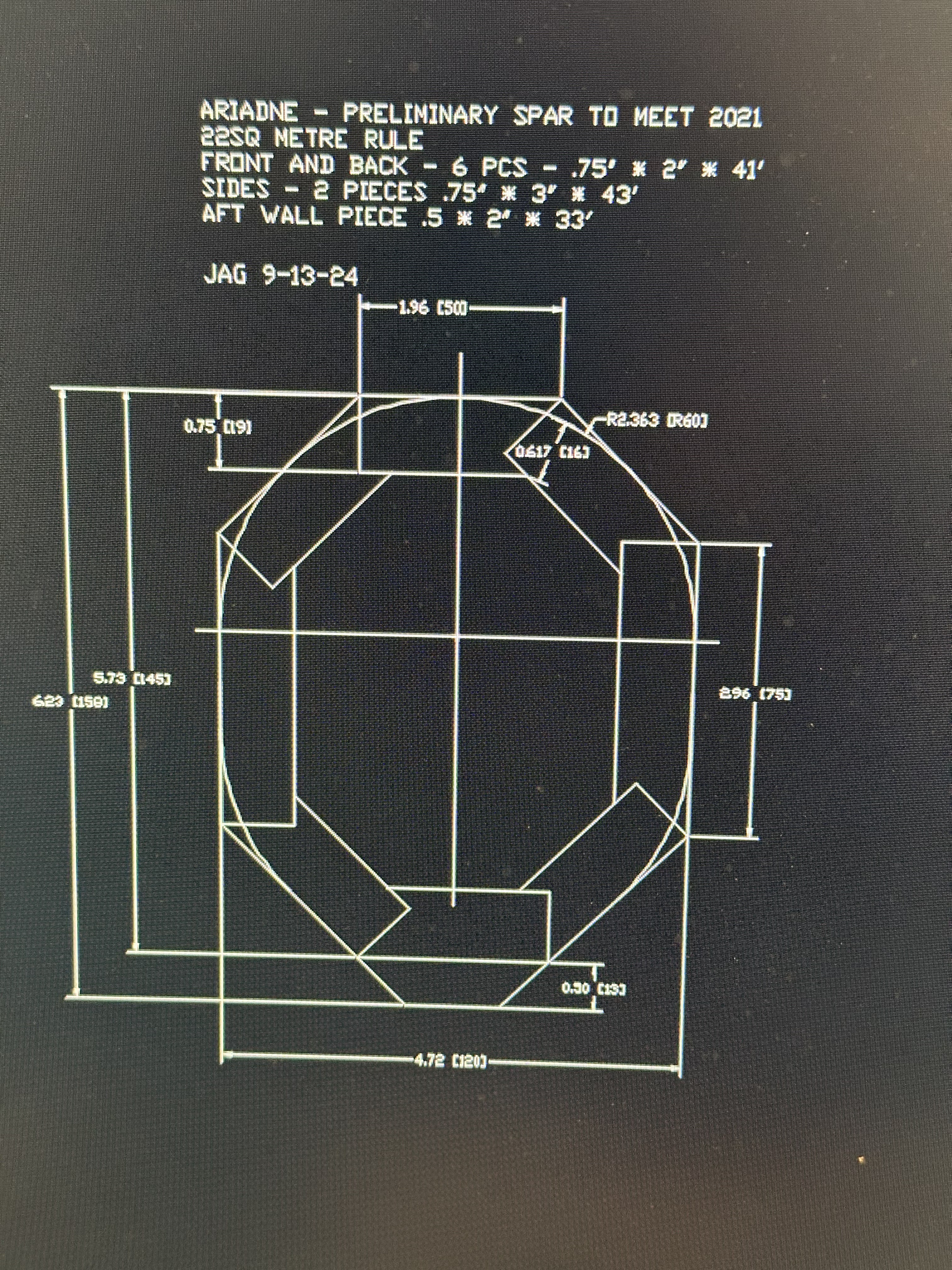
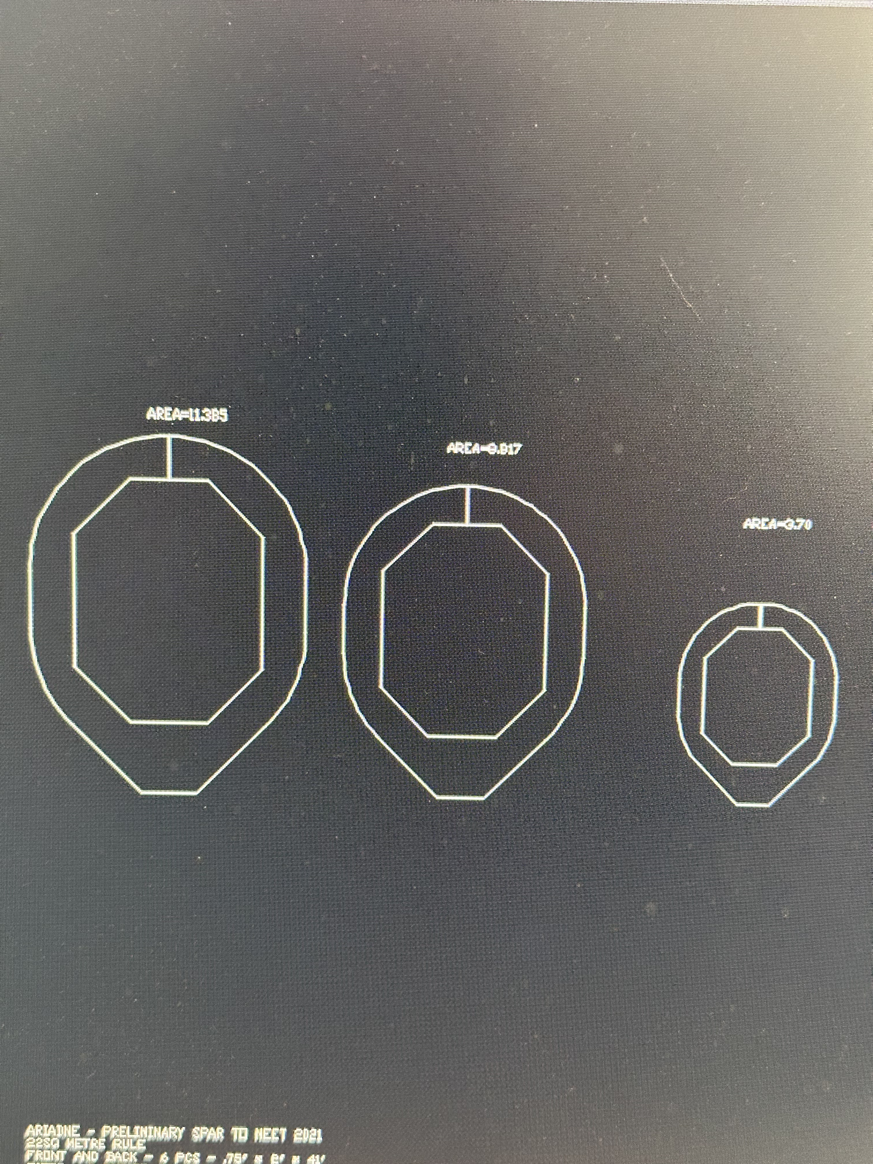
With the old mast thoroughly documented, we brought in some professional help. We hired an engineer to work with us on scantlings and design for the new spar. The 22 Square Meter class has a box rule that specifies minimum mast diameters, and one of the first things James discovered was that the old mast — the one that had been racing and cruising for ninety years — didn’t actually meet the rule.

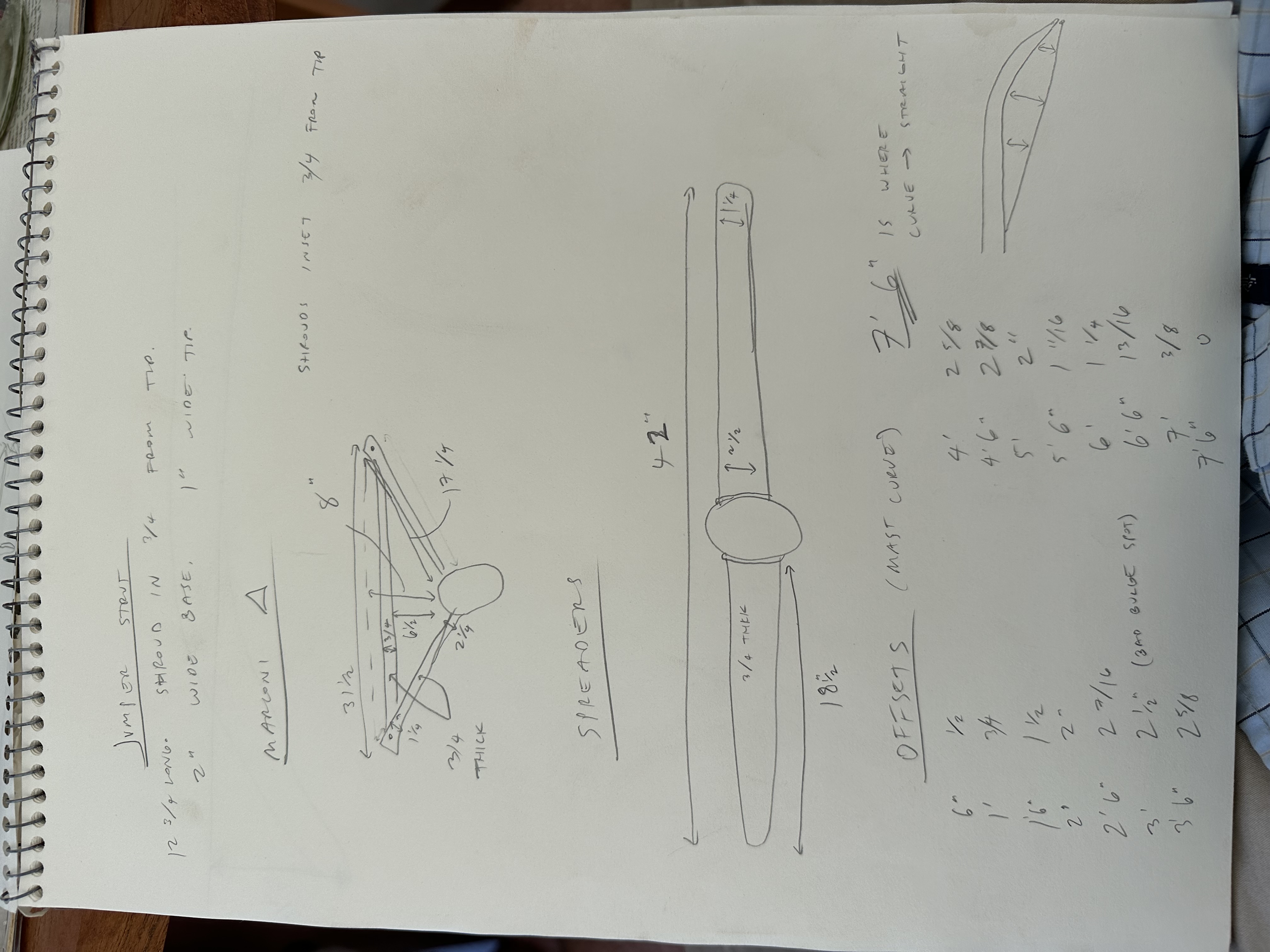
One of the most consequential design decisions was eliminating the jumper strut. The old mast had a jumper — a short strut near the masthead to stiffen the upper tip of the spar. But the jumper wasn’t original to the Swedish build. It was added at some point, probably to compensate for the mast’s deterioration. James helped us design a new section that was stiff enough on its own, eliminating the jumper and all its associated windage, weight, and complication.

CAD drawing of preliminary mast cross-section
This cross-section shows the stave layup in detail — side staves longer than the others to create an oval section, and an aft wall piece to form a teardrop and support the sail track.
CAD drawing showing three mast cross-sections at different stations
Three cross-sections at different positions along the mast, showing how the hollow spar tapers from its widest point near the partners up to the narrow masthead. It gets pretty delicate up at the top.

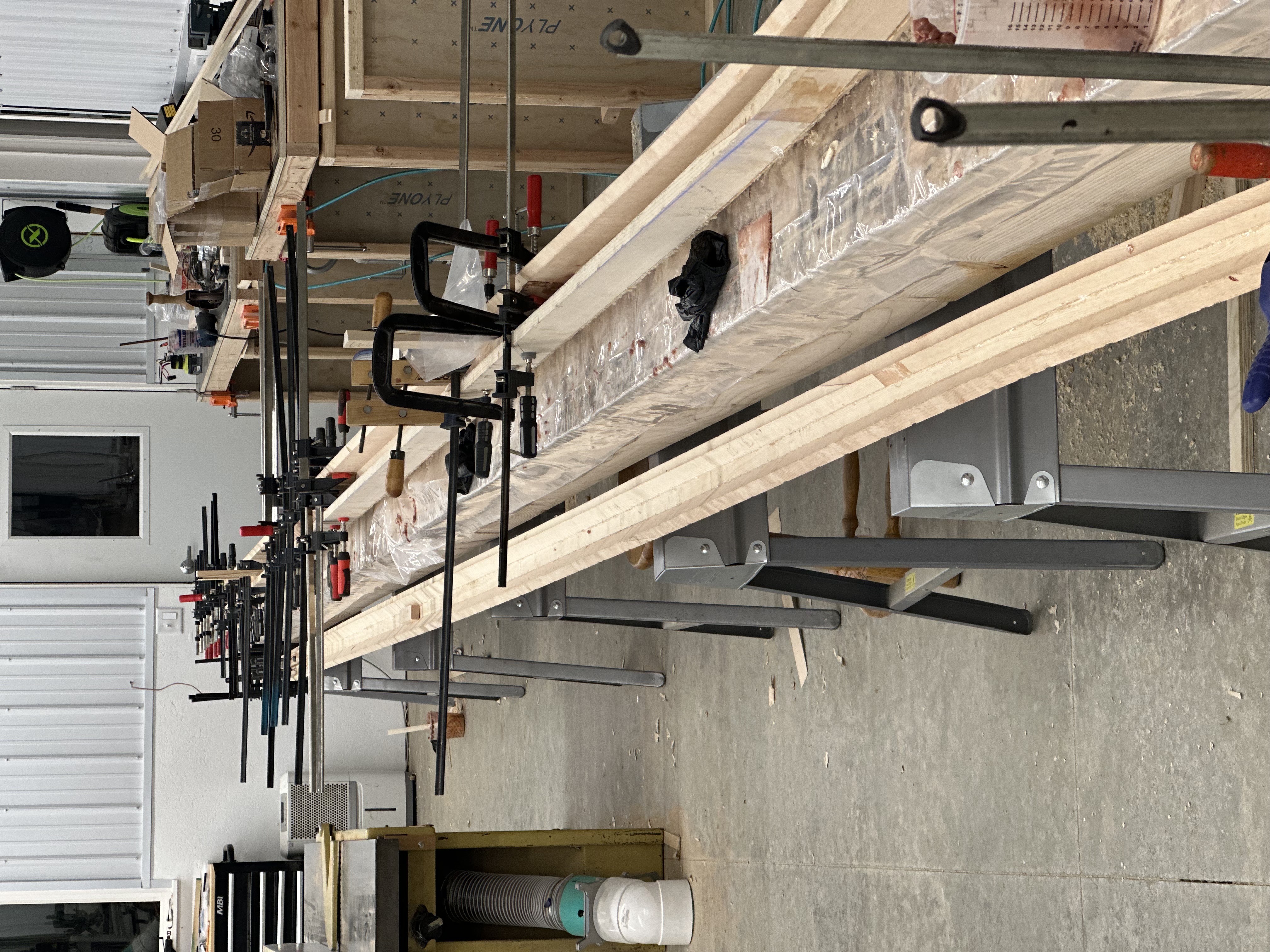
With mast sections in hand, we went out and bought a ton of Sitka spruce in 20’ lengths from the local iceboat club. They place a group buy every year for building boats. The stuff is hard to come by! Sitka spruce is the traditional choice for spars: straight-grained, light, strong, and available in clear lengths. With lumber in hand, we then mapped out every cut we’d make to every board.

Spreadsheet showing stave layout and scarfing schedule
The stave layout spreadsheet. Each row is a stave, each column is a position along the mast, and the colors indicate which lumber segment (A, B, or C) goes where. No single piece of lumber is forty feet long — the staves are scarfed together from shorter pieces, and this chart plans every joint.
Engineering spreadsheet showing mast dimensions at every station
The dimensional specification sheet: outer diameters, stave thicknesses, and inner diameters at every two-foot station from butt to tip. The mast tapers from 4.8 inches at the partners down to 2.0 inches at the masthead.

Test run

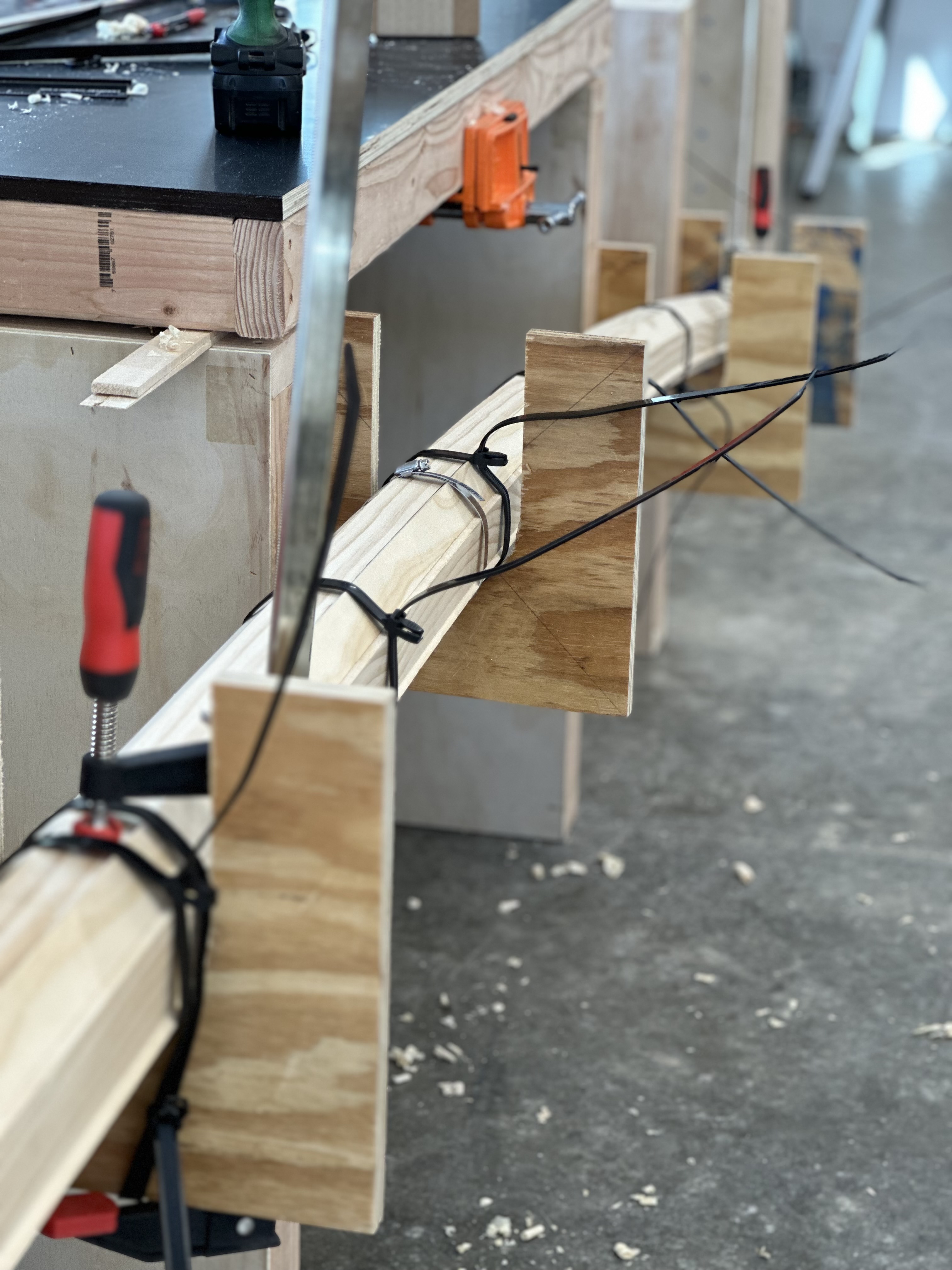
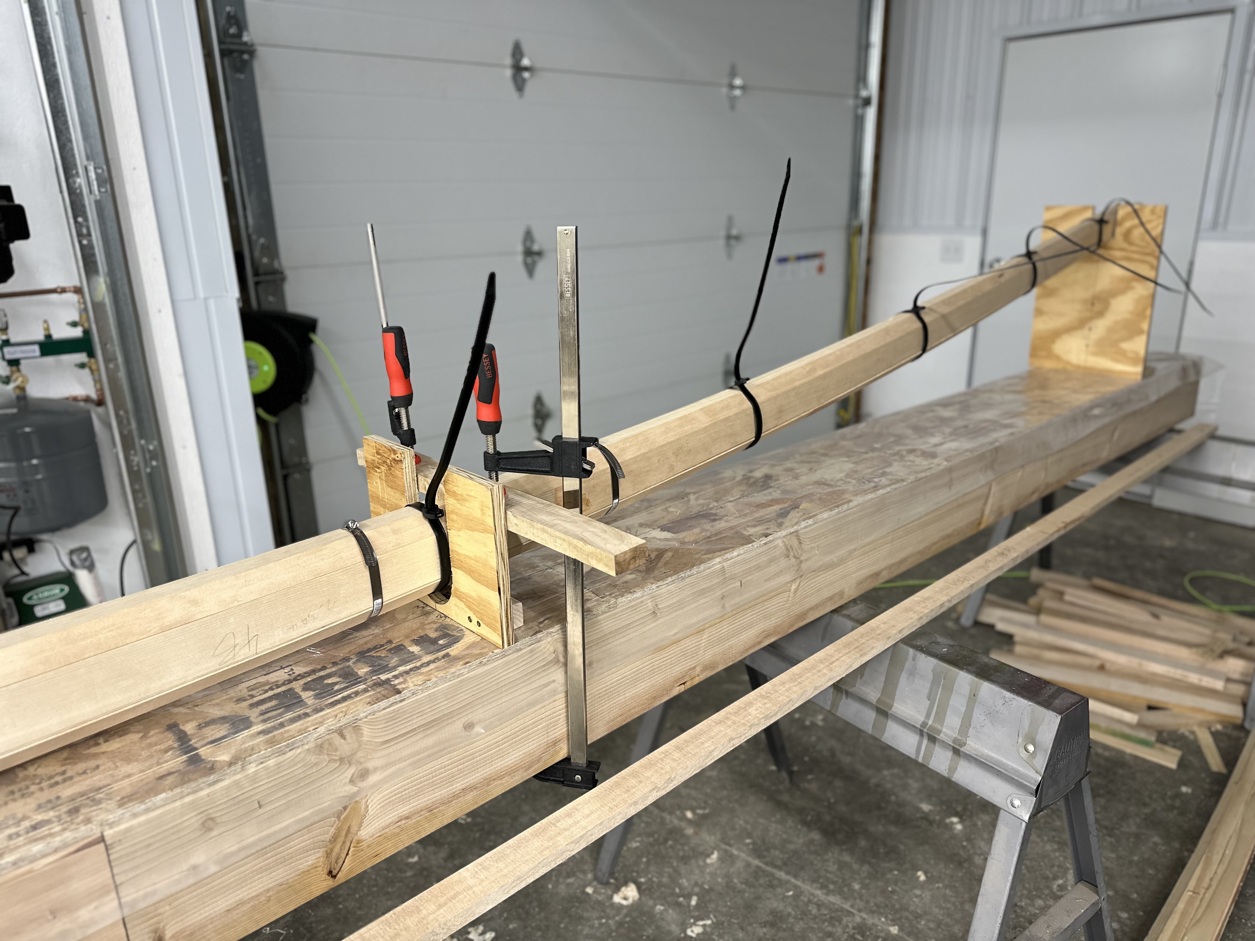
Before committing to the full-length glue-up, we built a test section to answer a few questions. We wanted to try out birdsmouth construction before committing to it — where the staves have mating V-grooves along their edges instead of flat joints — and we wanted to see what would happen if we glued in a pre-bend at the mast tip. How much would the bend spring back after the clamps came off? Would the curve introduce voids between the staves? The test piece also let us experiment with clamping methods.
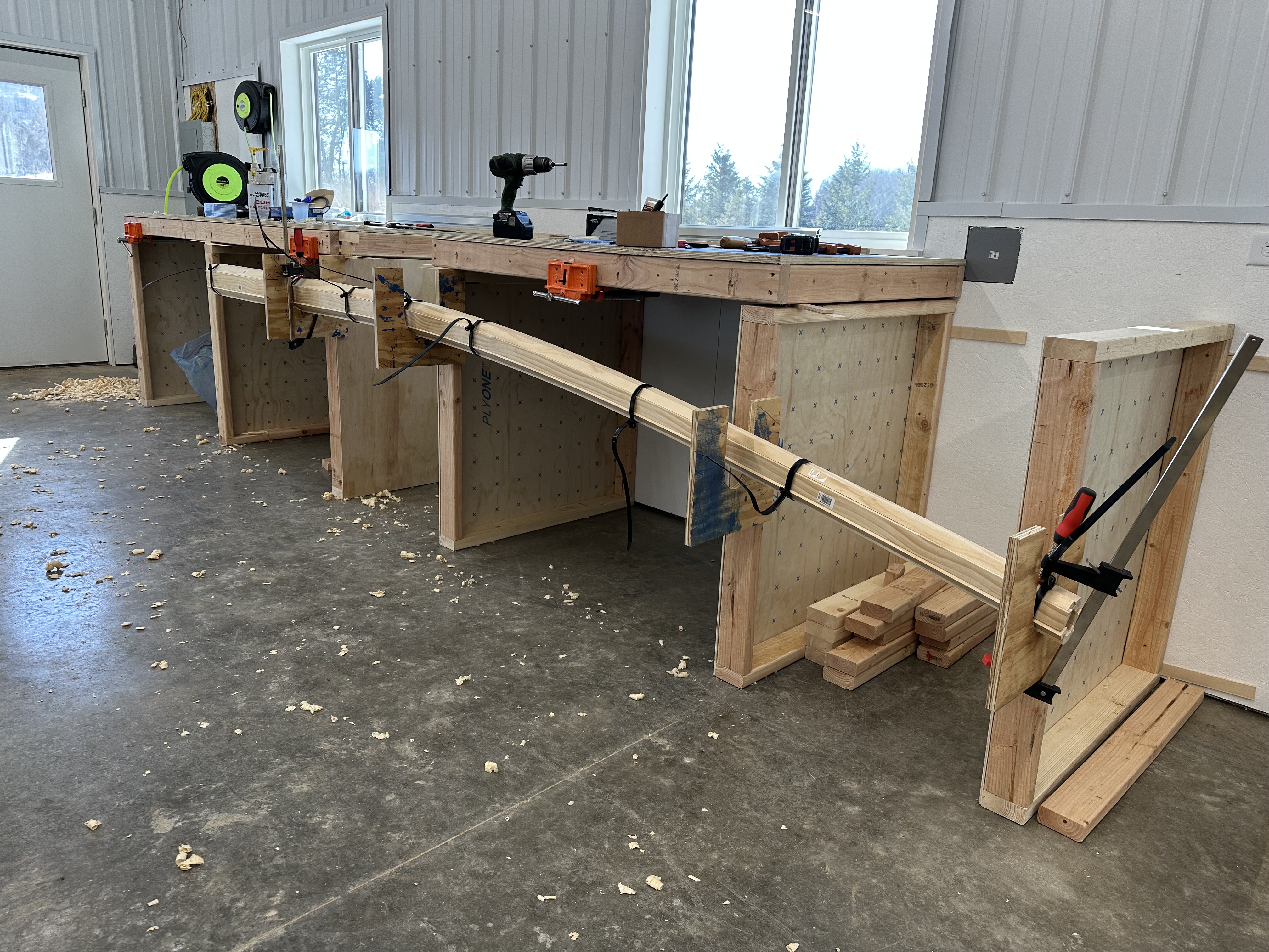
Test section of birdsmouth mast construction in wooden cradles
The test section mocked up in its cradles. This was our trial run for birdsmouth construction and for gluing in a pre-bend to the mast tip.
Test mast section clamped with hose clamps and zip ties
Hose clamps and zip ties on the test piece. We tried both to see which applied more even pressure around the circumference. The zip ties were easier to get on but applied much less force. We ended up using exclusively hose clamps for the real thing.
Cut-off from the tip end of the test section showing tight glue lines
A cut-off from the tip end of the test section. The glue lines between the staves are very tight — exactly what we wanted to see.

Built like a barrel

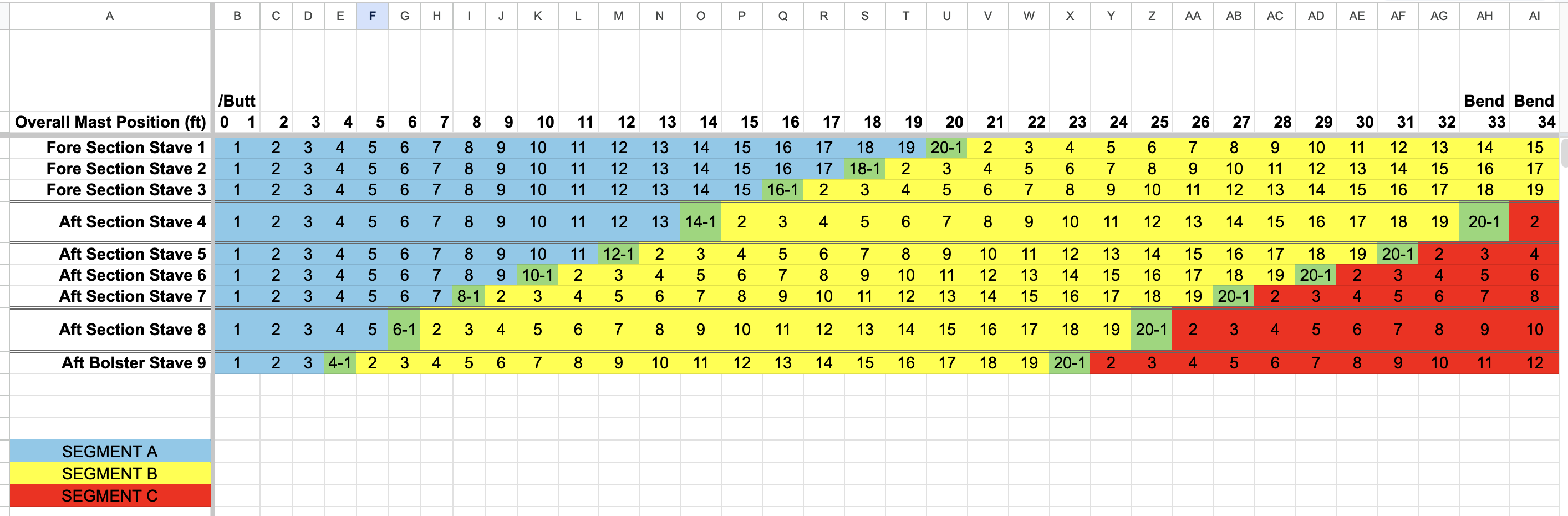
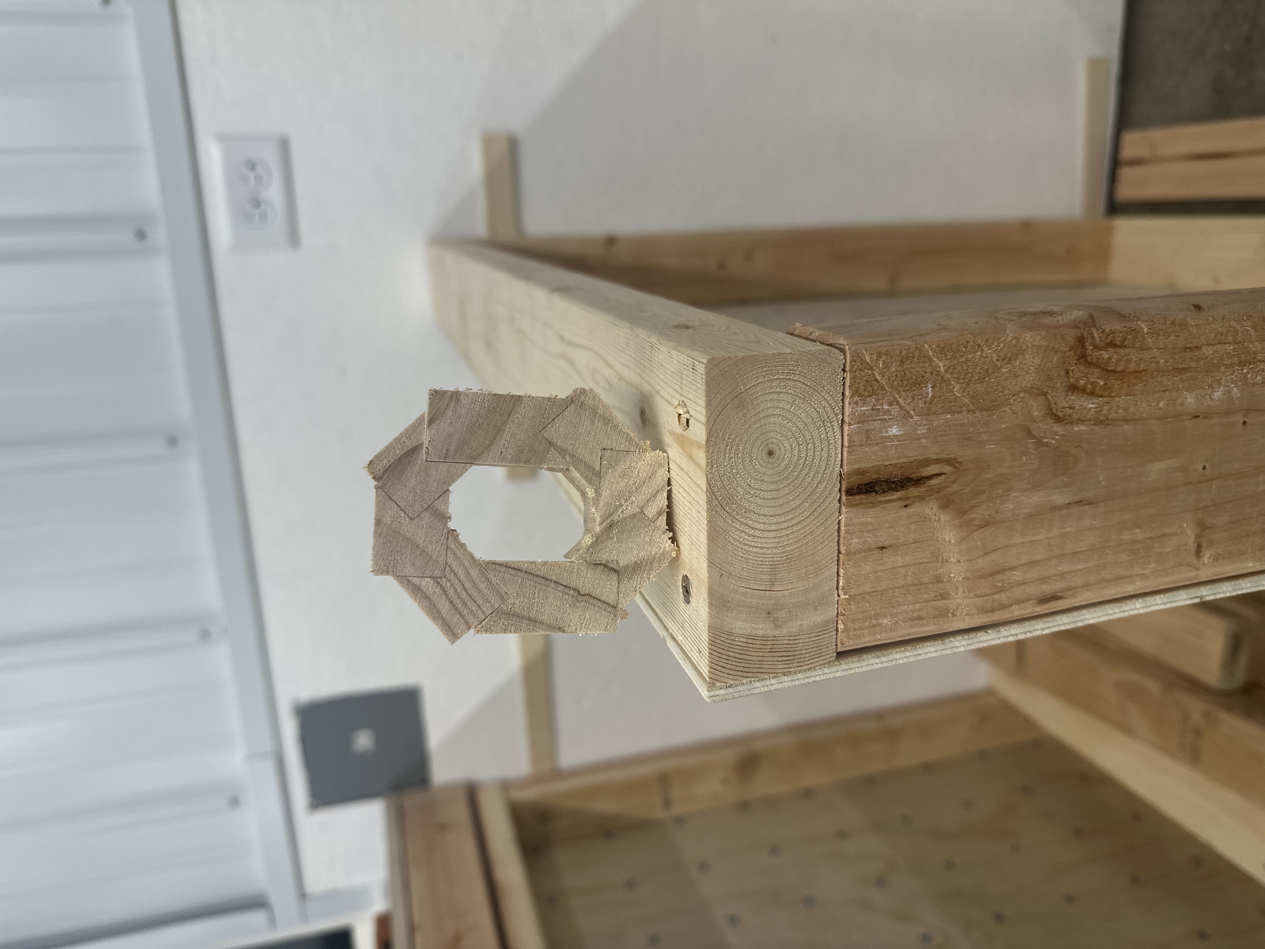
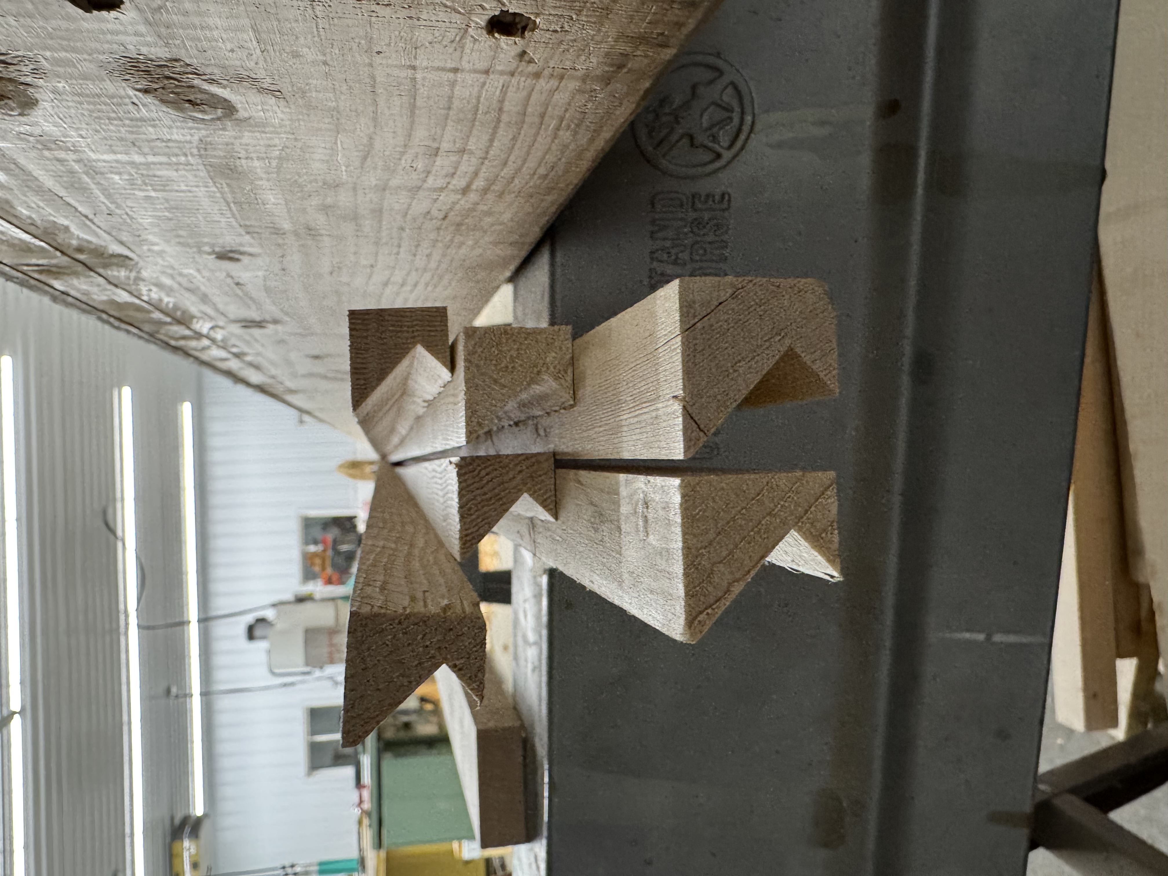
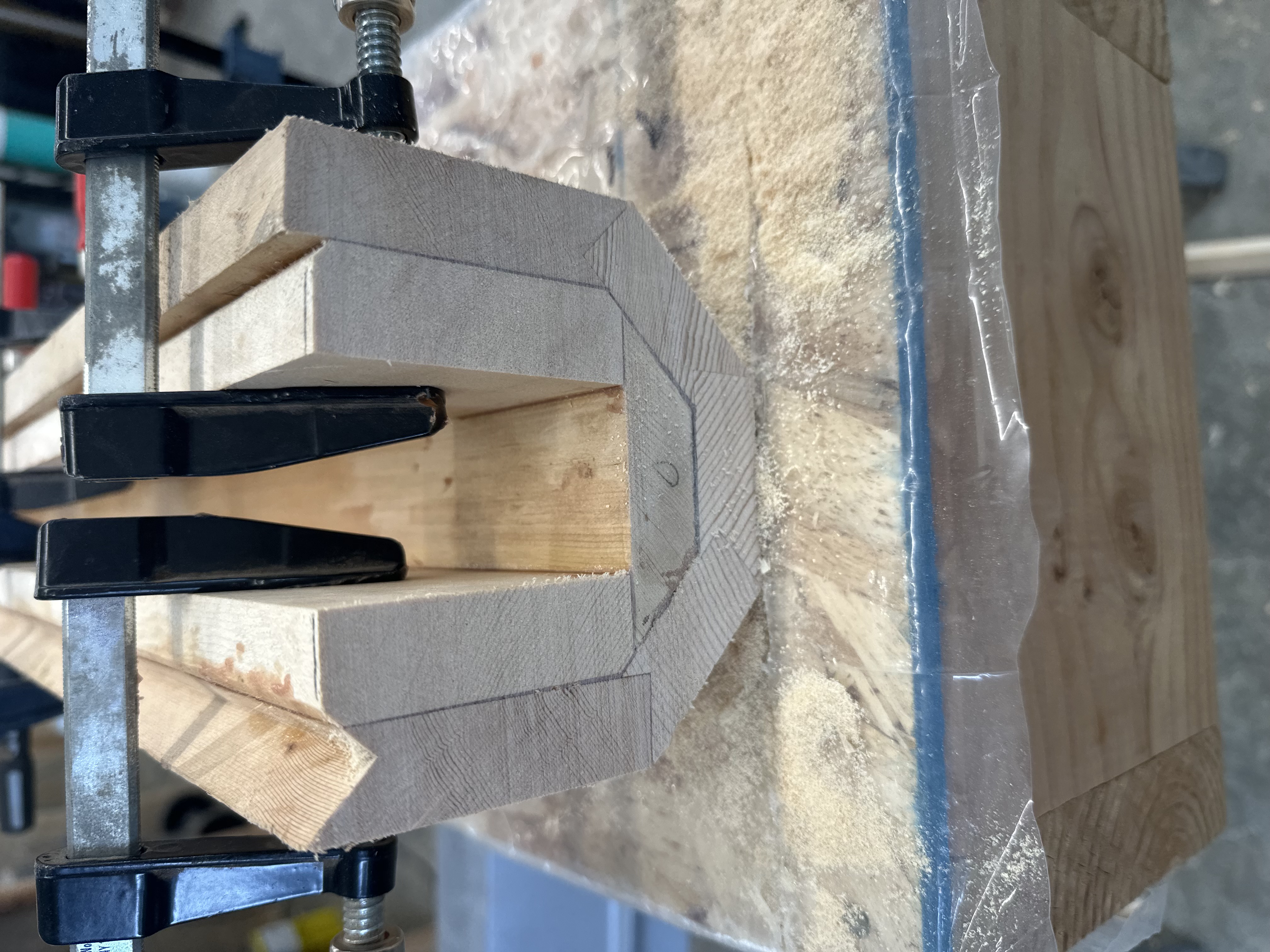
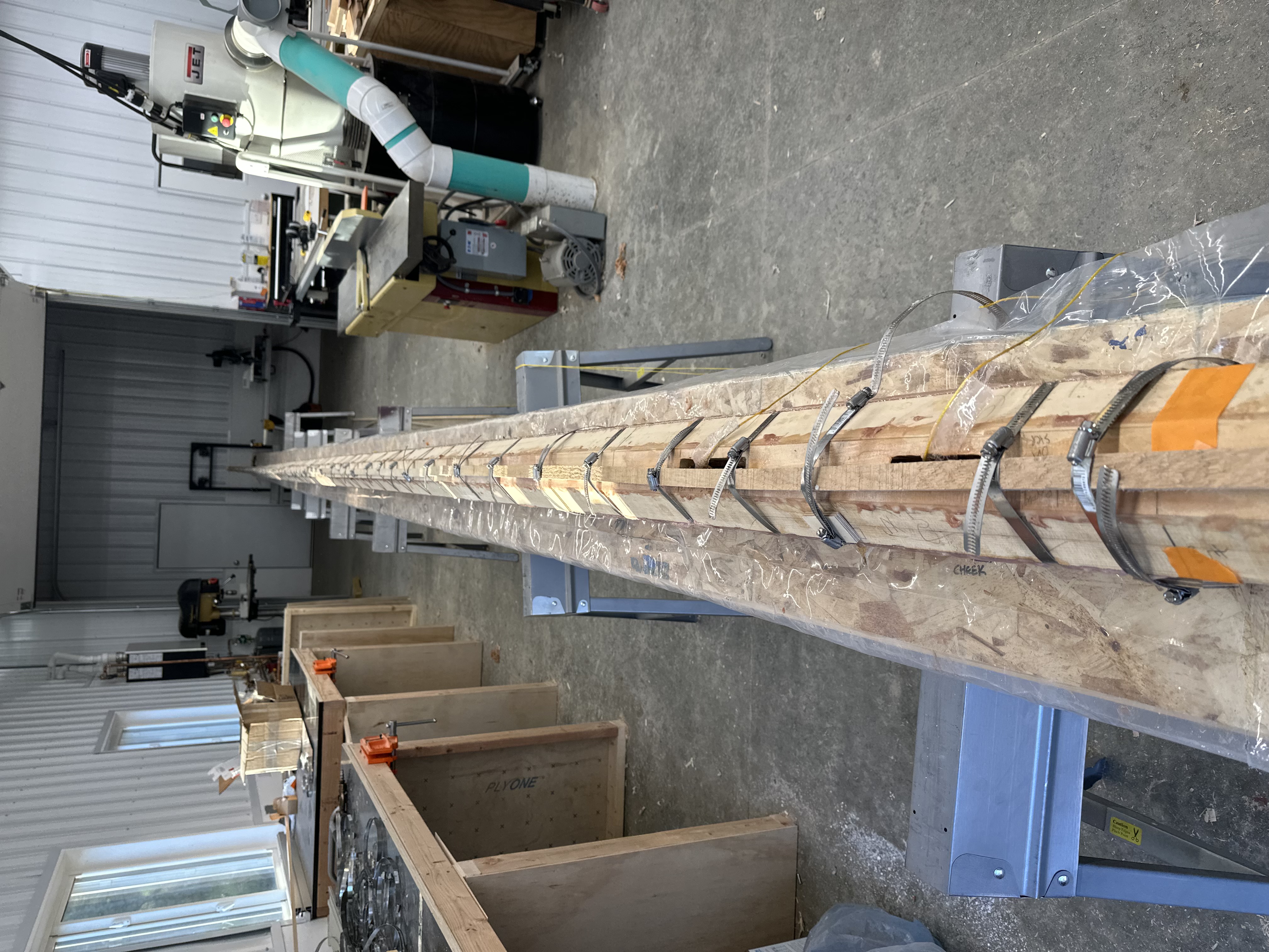
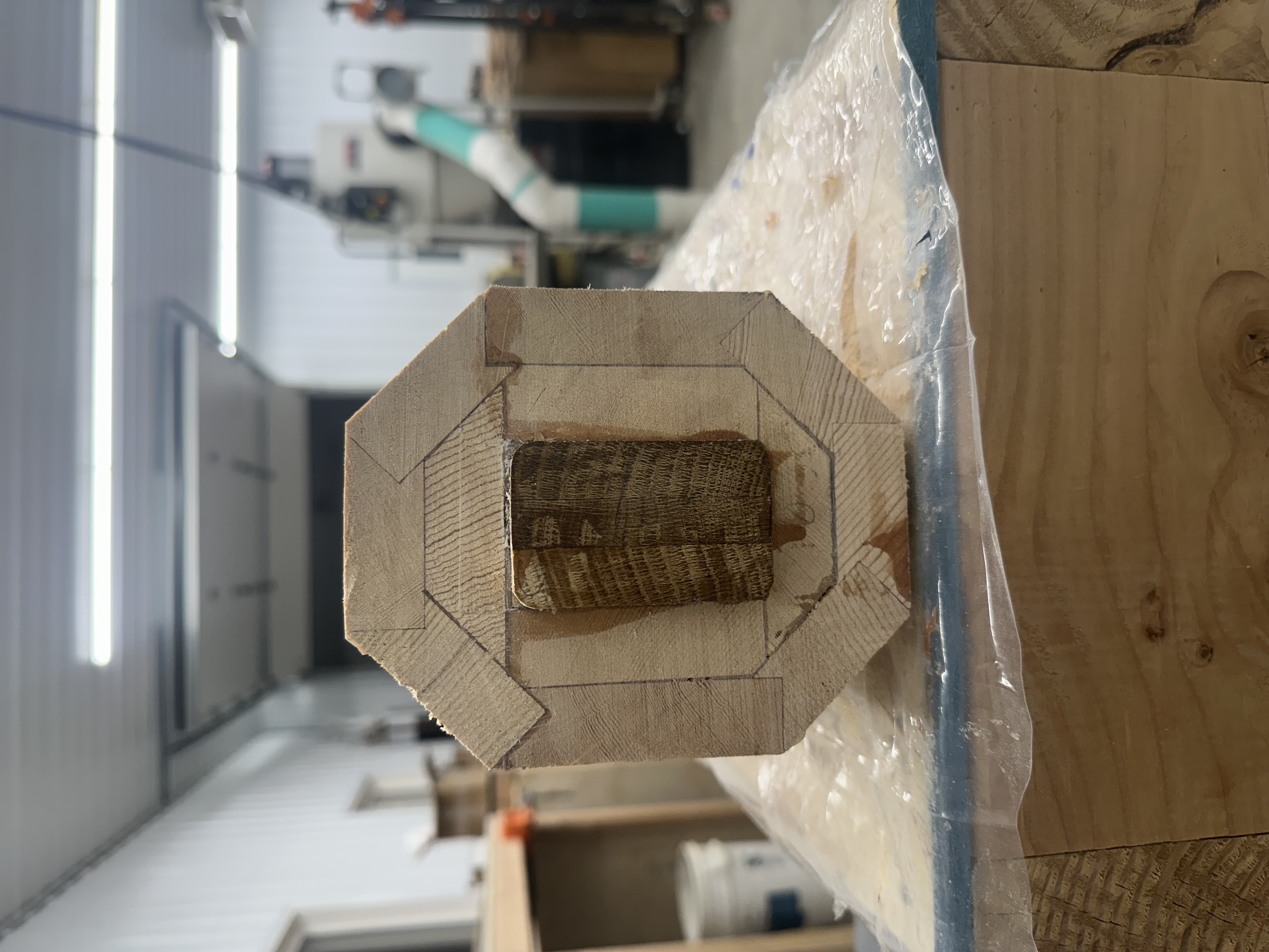
A mast looks like a long stick, but it’s actually built like a barrel. The new spar is hollow — eight spruce staves glued up around a central cavity, like coopering a cask. The staves taper in both width and thickness along their forty-foot run, so the finished spar has the correct cross-section at every point from heel to masthead.

Each stave is assembled from two or three shorter pieces joined with epoxied scarf joints — long, angled glue joints that are effectively invisible once faired and stronger than the surrounding wood.
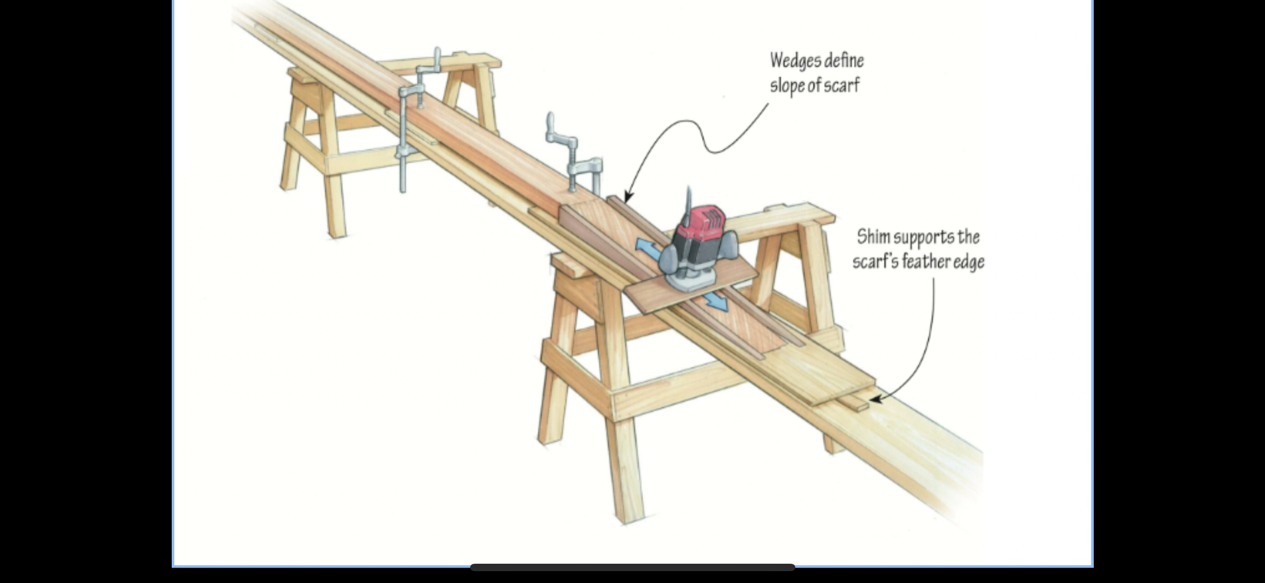
Illustrated diagram of a scarfing jig
A scarfing jig from the reference books. Wedges define the slope of the scarf, and a shim supports the feather edge during cutting. The joint typically runs 8:1 or 12:1 — meaning the angled overlap is eight to twelve times the thickness of the stock. This time we actually ended up cutting the scarfs on the bandsaw, however, with excellent results.
Cutting the birdsmouth on the shaper
Milling the birdsmouth on the shaper. The staves are over forty feet long at this point, so they had to run out the door.
End-grain cross-section of mast staves at the tip
Cross-section of the staves at the very tip of the mast. The birdsmouth is quite prominent up here where the staves are at their narrowest.
Cutting the taper into mast staves with hand planes
Checking the tapers we cut in with a power planer and long-soled hand planes.
Pile of Sitka spruce shavings on the workshop floor
The evidence. Sitka spruce shavings. The byproduct of fairing staves to their final dimensions. The shavings smell great and are very effective fire starters. Relatedly: clean up your shop every night to avoid a fire!

Initial assembly

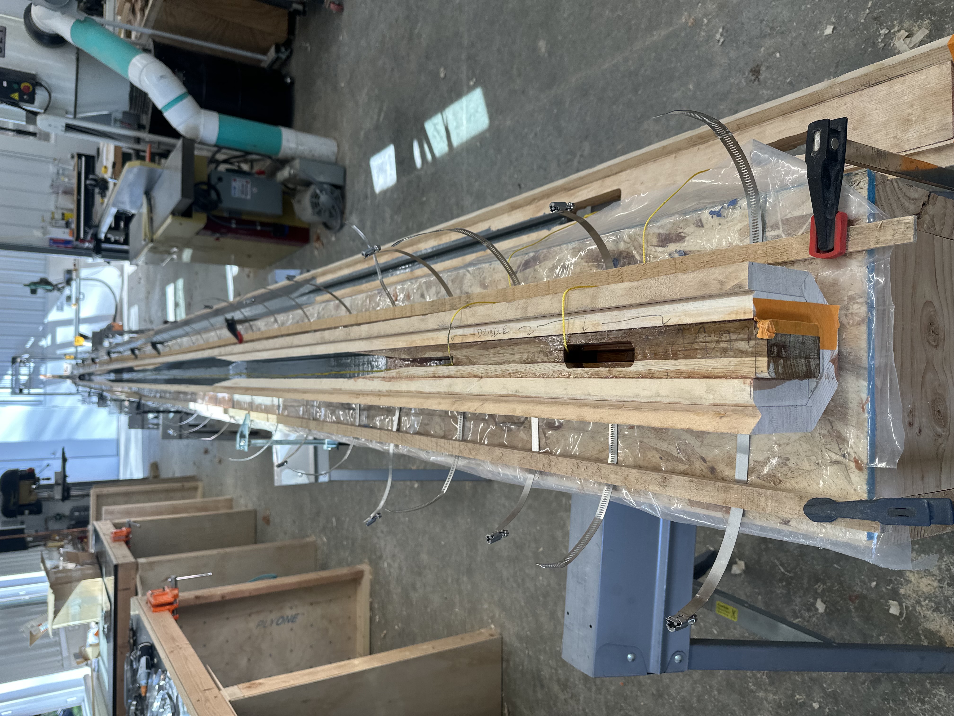
Building our mast was a multi-stage process. The first glue-up joined the staves into two halves — five staves in the larger half, three in the smaller — leaving the joints between the halves unglued so we could take it apart. After this step, we needed the interior to remain accessible for interior blocking, rigging, and sealing.

Mast staves dry-fitted with internal blocking
Dry-fitting the staves clamped to station molds at the mast tip. These plywood molds were screwed to our strongback and define both alignment and tip bend.
End-grain view between first and final glue-up
Between the initial and final glue-ups. The bottom half has five of the eight staves; the aft three are the other half. We left the two joints between the halves unglued during the first round so we could work on the interior before closing the mast up. This is the larger half of the mast butt with three additional pieces of internal blocking glued in.

Internals

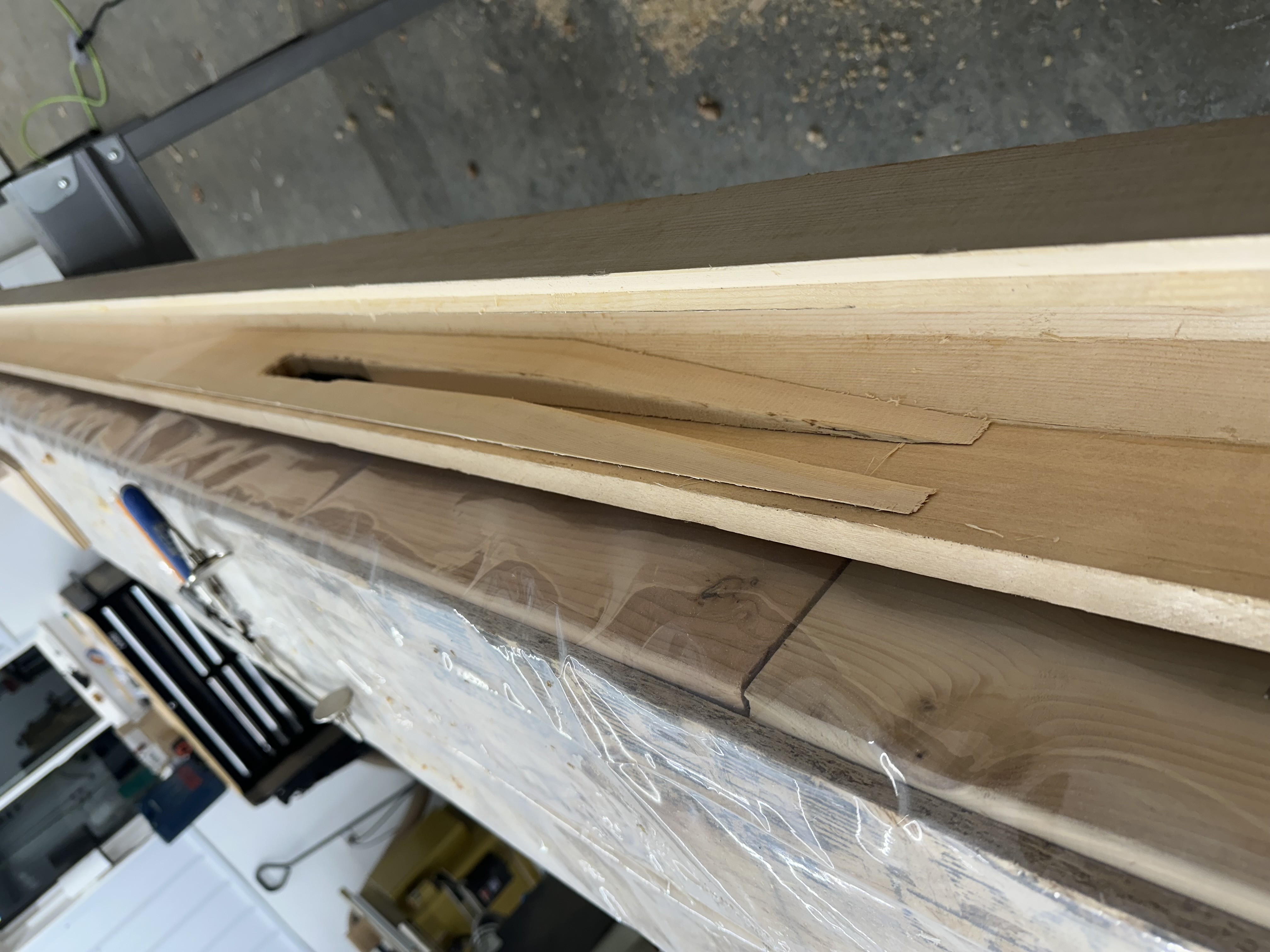
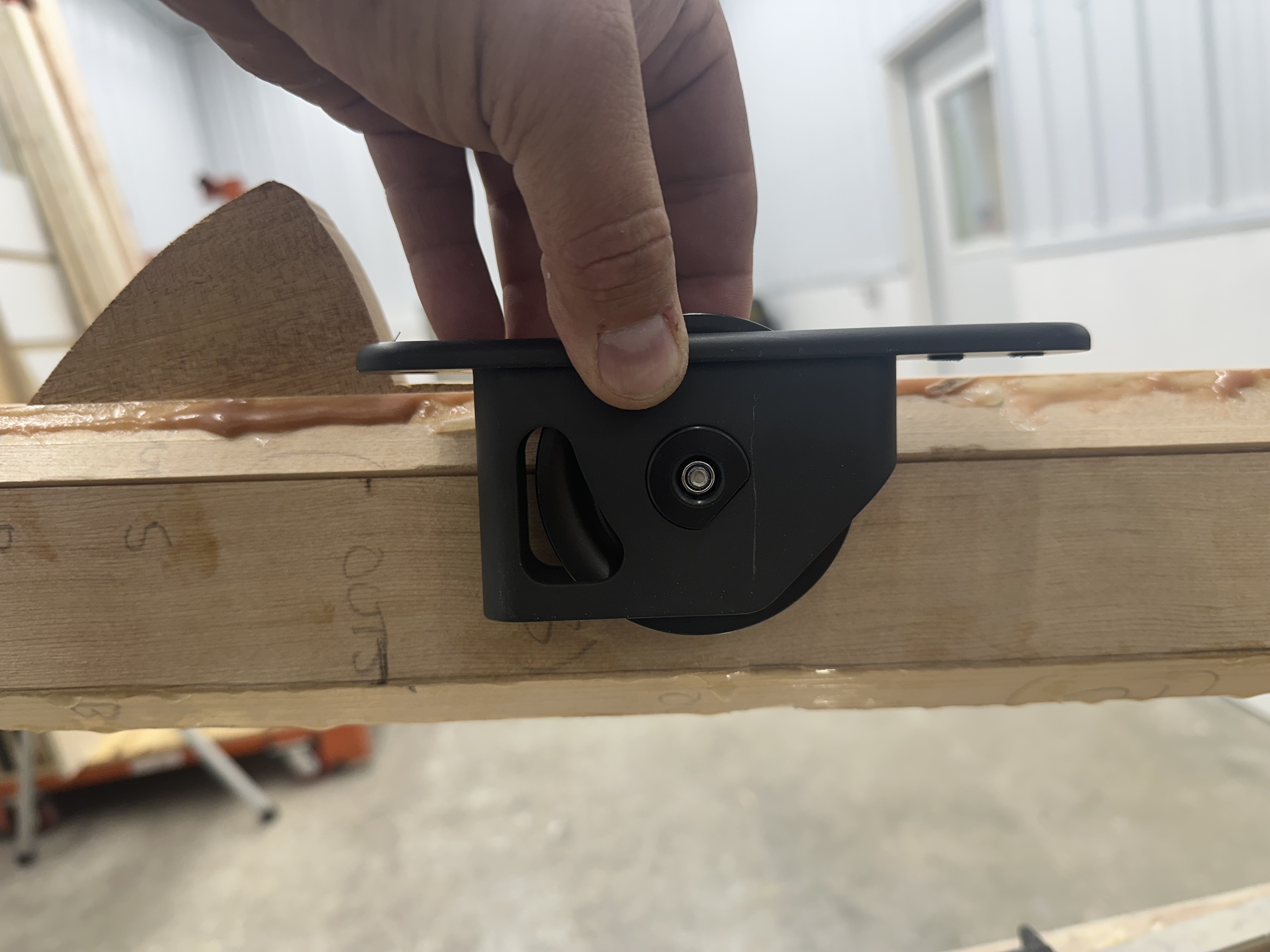
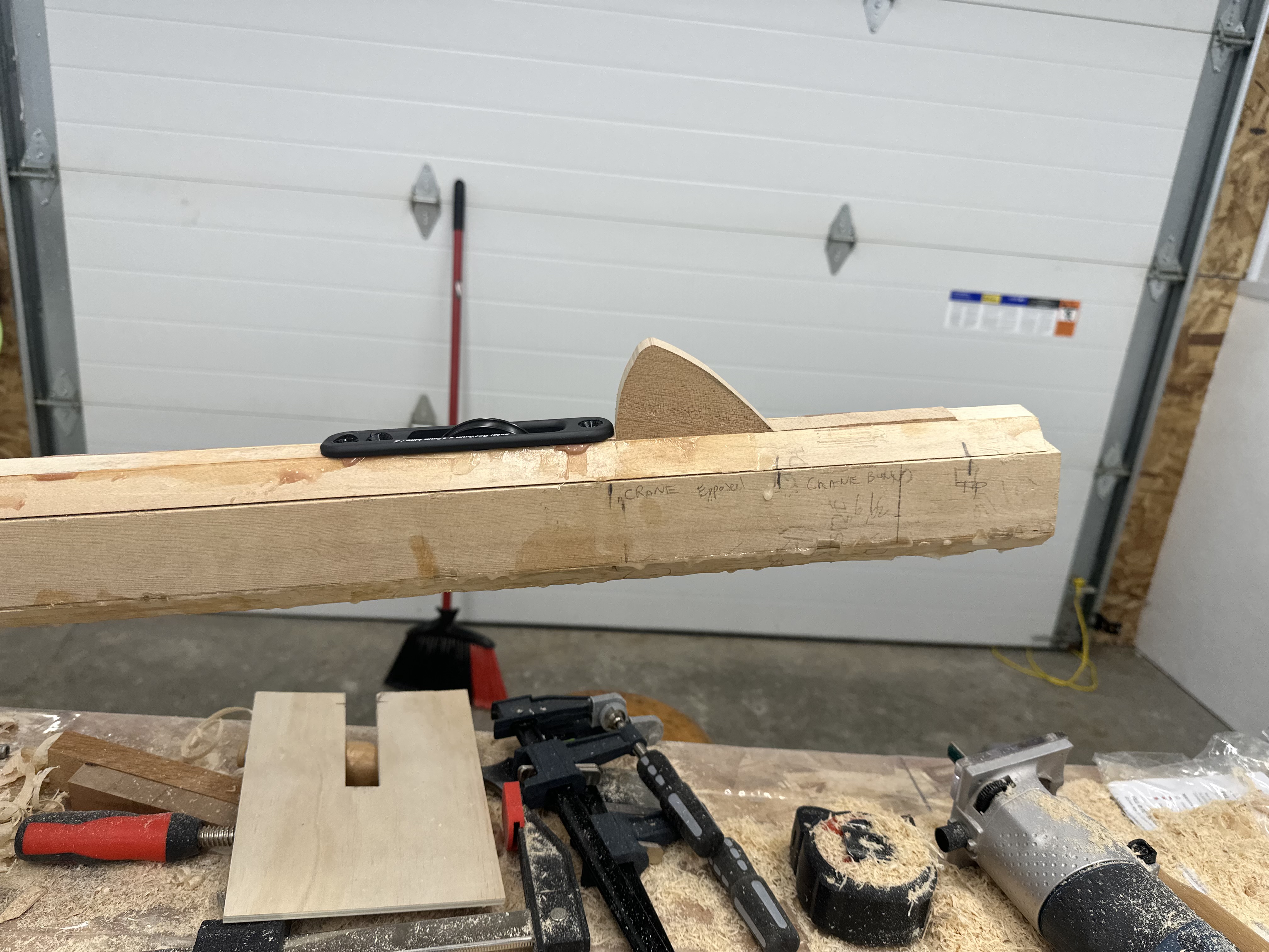
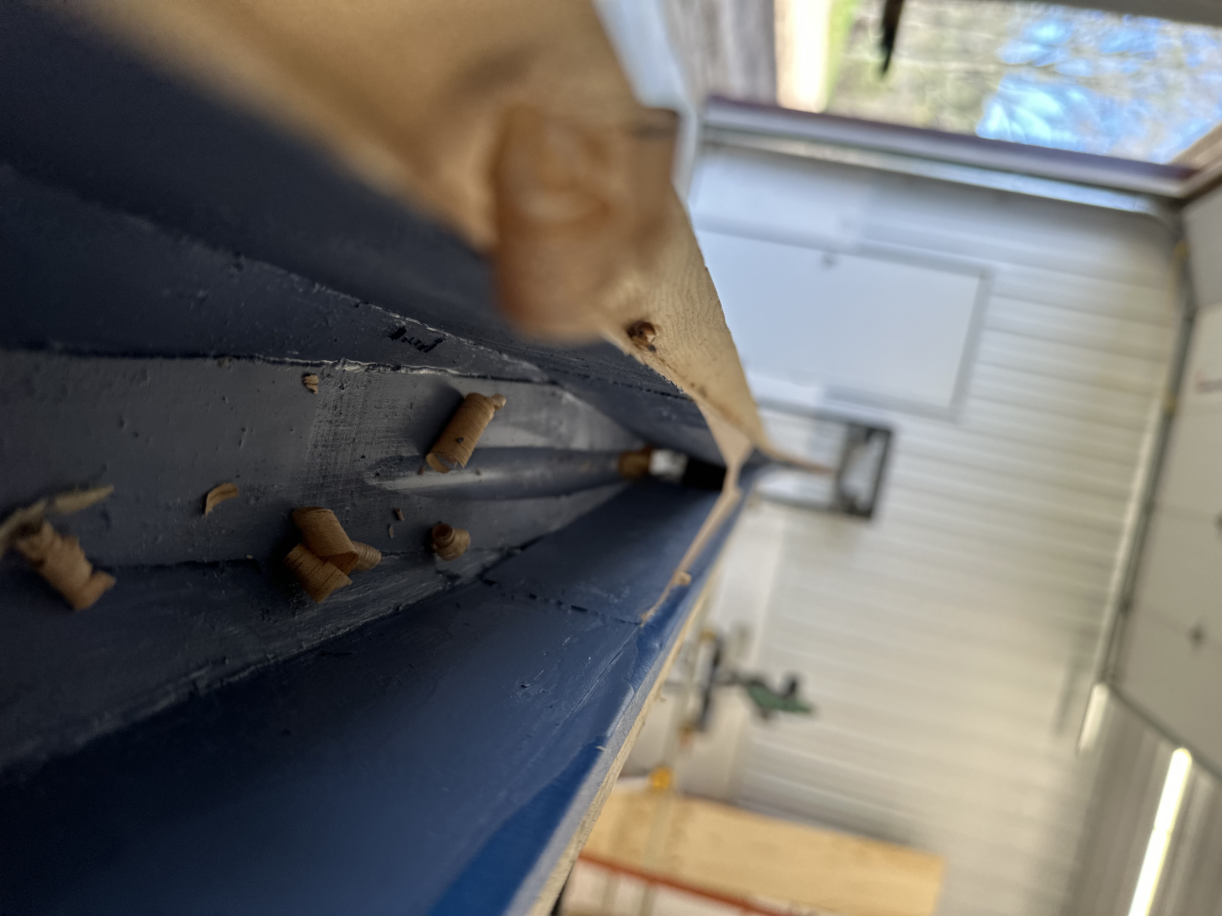
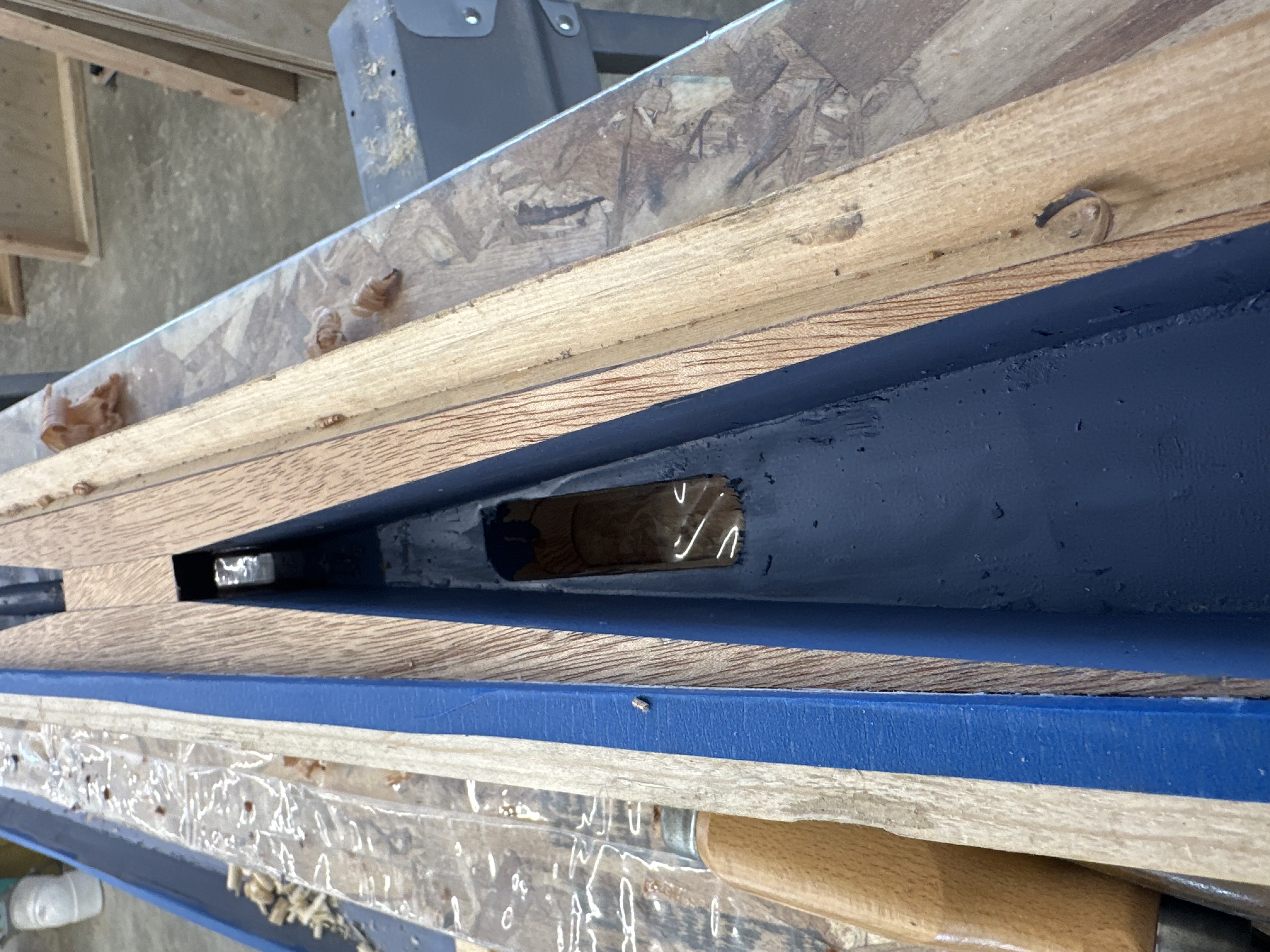
From the outside, a mast looks extremely simple, and sometimes it is. But especially for larger boats it’s really a pretty complicated construction. The halyards run internally: in through sheave boxes at the masthead, down through the hollow core, and out through exit slots lower on the spar.

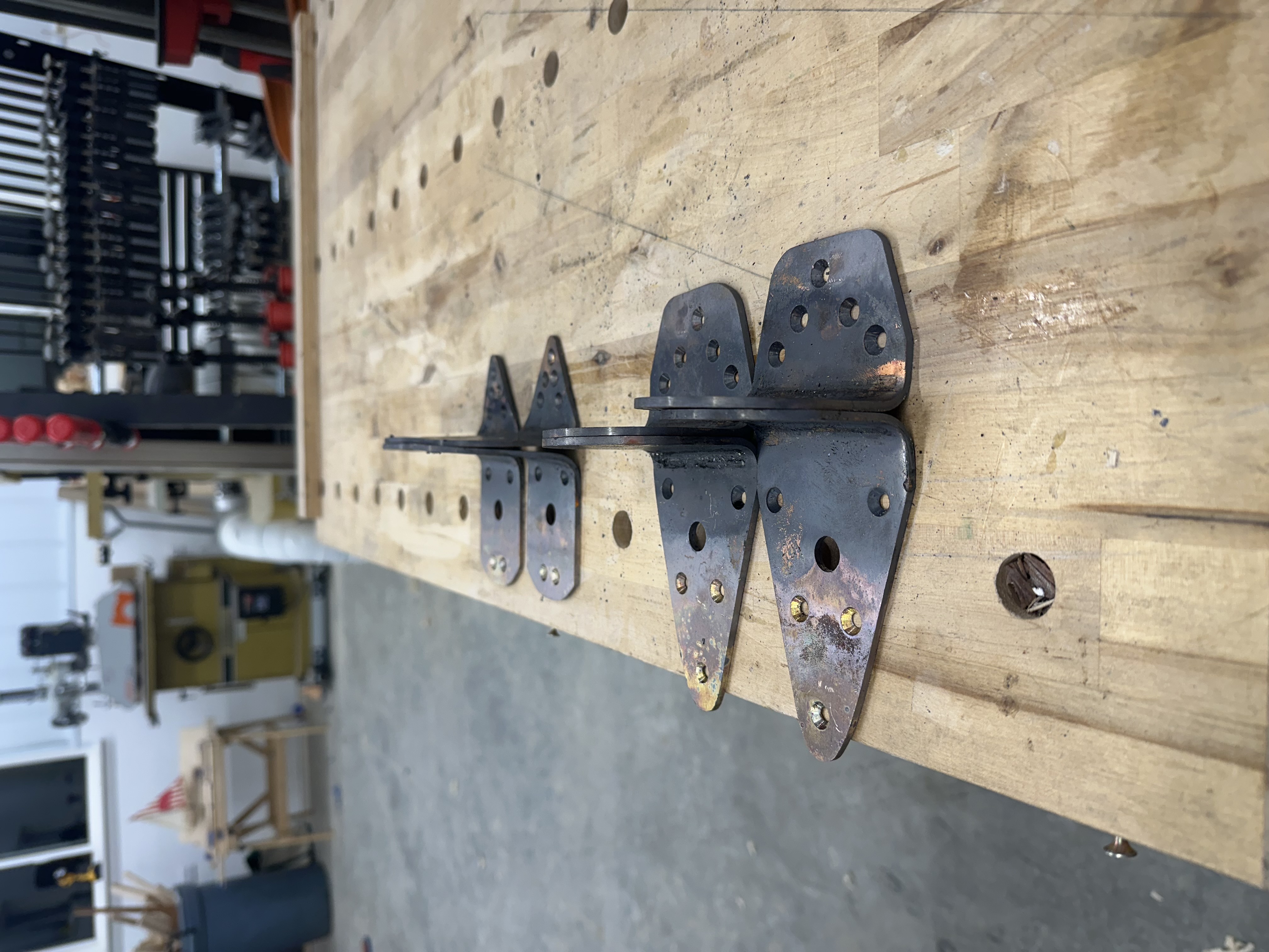
There is also a great deal of internal blocking. At every point where the rigging applies a load — shroud tangs, forestay, backstay, halyard sheaves — there needs to be solid structure inside the mast to resist compression loads. We used G10 fiberglass tube for some of these reinforcement points. G10 is strong, dimensionally stable, and bonds well with epoxy. But it has one significant drawback: the cut edges expose glass fibers, and if a halyard runs across those fibers, the glass threads work into the rope and destroy your hands. So every G10 element has to be positioned so that the halyards run free without ever touching it.

G10 fiberglass tube epoxied into mast for shroud termination
A G10 tube epoxied into the mast wall at a shroud termination point. A bolt passes through the tube and secures a pair of Colligo Cheeky Tangs — one on each side of the mast — where the standing rigging terminates. The tube spreads the compression load across a wide area of the mast wall.
Mock-up of blocking around the jib halyard exit
A mock-up of blocking around the jib halyard exit. The blocking is tapered to avoid point-loading the mast wall, and there's a clear space for the halyard to run between them.
Halyard exit box being fitted into mast slot
A halyard exit box being mocked up against its slot. This piece gets screwed into the mast wall and provides a smooth, reinforced opening for the halyard to exit the spar.
Partially assembled mast showing halyard exit and annotations
The mast with a halyard exit installed. the mahogany backstay crane has also been epoxied in place and will support a looped backstay termination.
Wooden sheave box components with bronze sheave
Mast blocking at the base of the mast that supports the main halyard exit block and drains moisture from the mast interior. This was built in two halves and glued together.

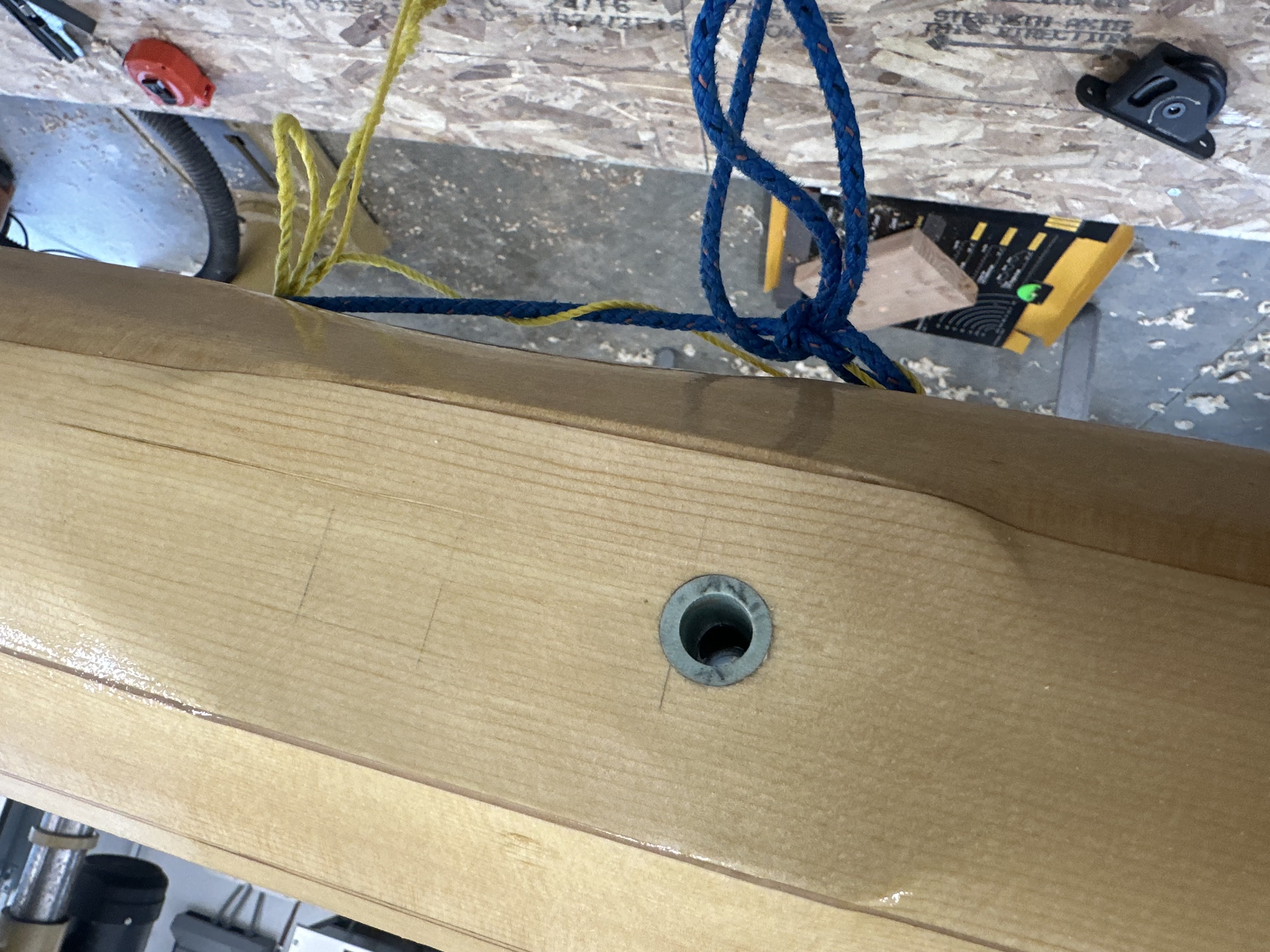
Once all the blocking and hardware is positioned, everything gets glued in and the interior gets a coat of bilge paint to protect against condensation moisture.

Gluing interior blocking into the larger mast half
Gluing interior blocking into the larger half of the mast assembly.
Interior of the new mast showing blocking and bilge paint
Looking into the new mast's interior. The dark coating is bilge paint — applied to protect the inside of the spar from moisture that condenses inside the hollow core. Blocking and the halyard channel are visible along the length.
New mast interior showing halyard channel and internal blocking
Another view of the interior plumbing. The halyard channel runs along the center, and the internal blocking that supports shroud loads and hardware is visible at intervals. Everything inside gets bilge paint before the mast is closed up.

Final assembly

With the blocking installed, the interior painted, and halyard chase lines threaded through the core, it’s time to close the mast up for good. This is the point of no return — once the two halves come together with epoxy, whatever is inside stays inside.

Mast prepared for final glue-up with blocking and halyard chase lines
Ready. All the blocking is in, the interior has been painted, and yellow chase lines for the halyards are threaded through the core.
The mast final glue-up
The final glue-up, with the two halves joined permanently. A mortise for a halyard exit blog is visible near the end.
Octagonal mast cross-section with hollow core visible
The octagonal cross-section in profile, with a rounded tenon visible in the center that will mate to a G10 reinforcement plate at the very bottom of the mast.

Shaping

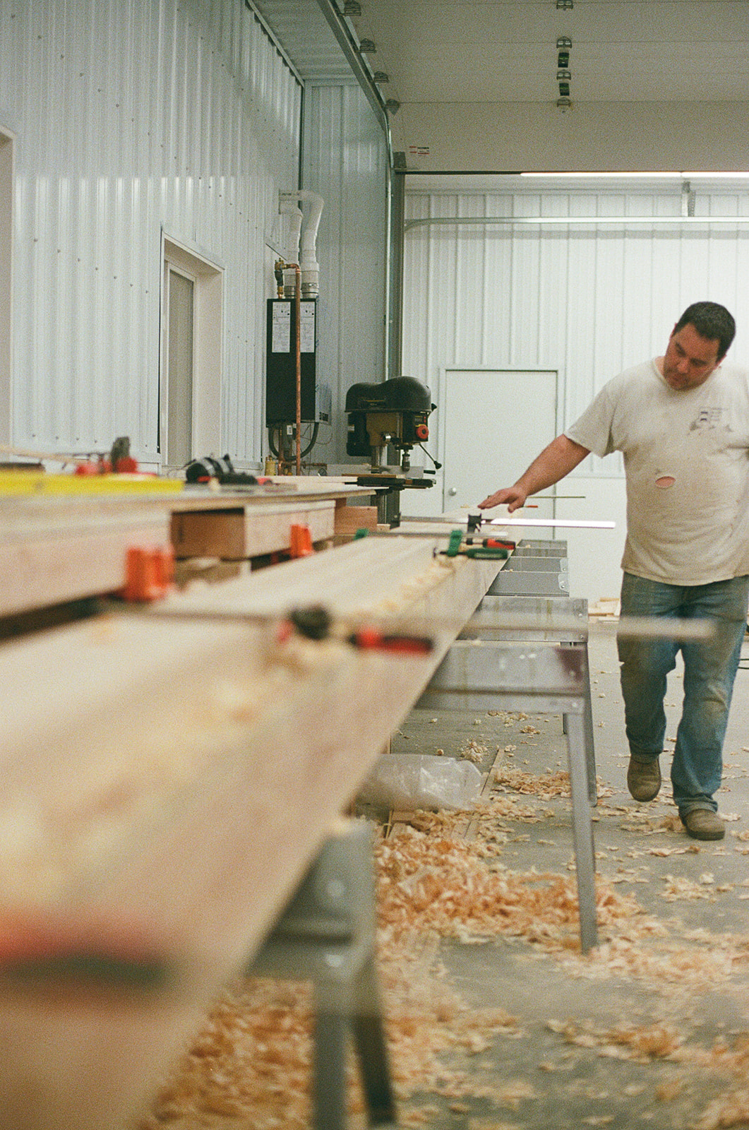
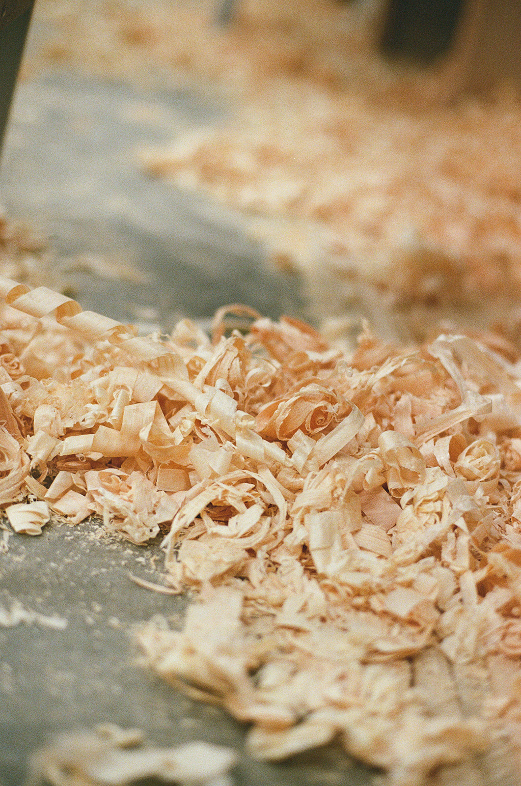
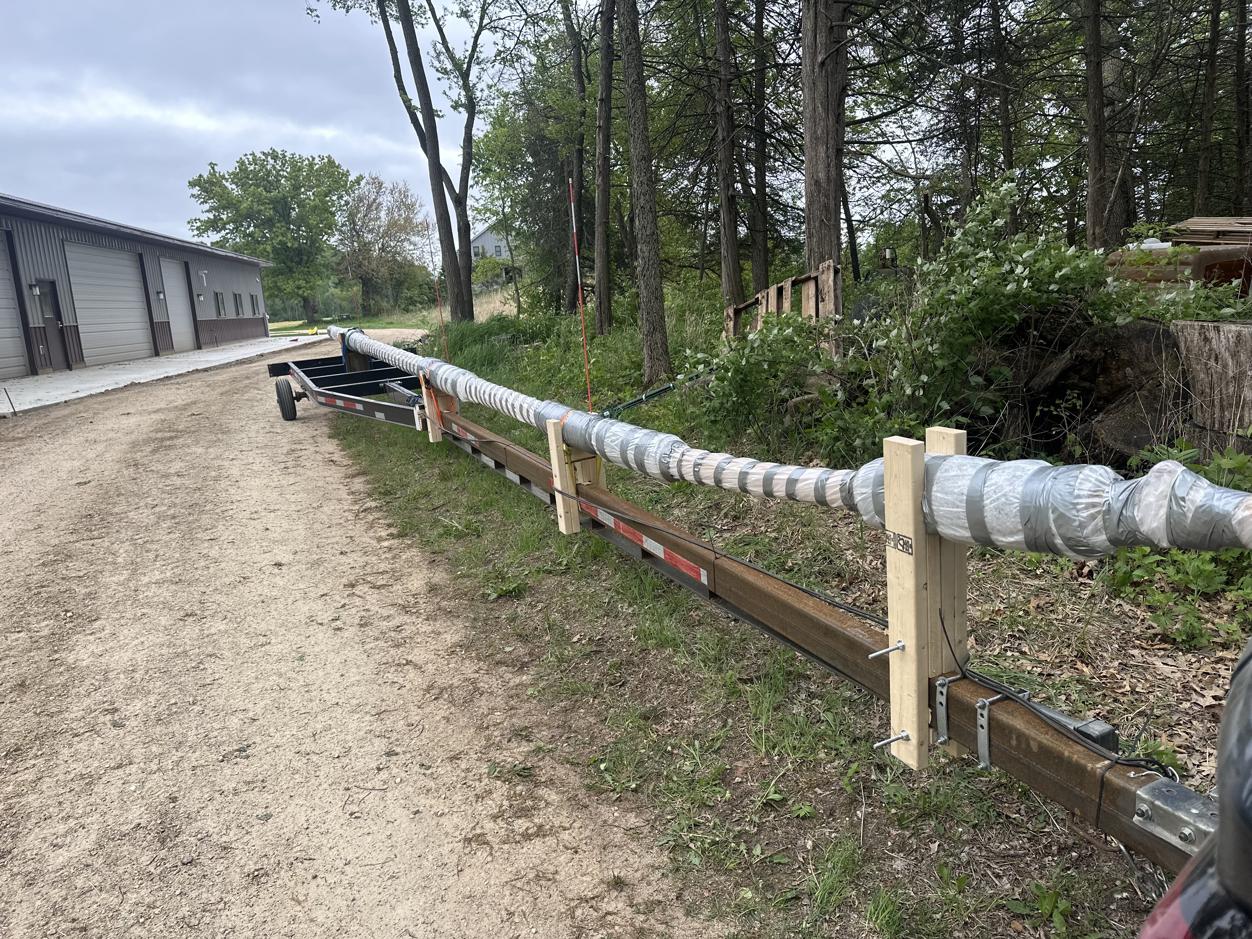
With the mast closed up, it’s still a rough octagonal blank. Shaping is mostly hand tools — a jack plane or jointer plane takes the corners off the octagon to make it sixteen-sided, then 32 sided, then you sand and plane to the desired ellipse. The taper runs continuously from butt to tip, which means the shaping has to blend along the full forty-foot length, except for sections that remain octagonal for hardware attachment! At the very end you go by eye and by running your hand along the spar.

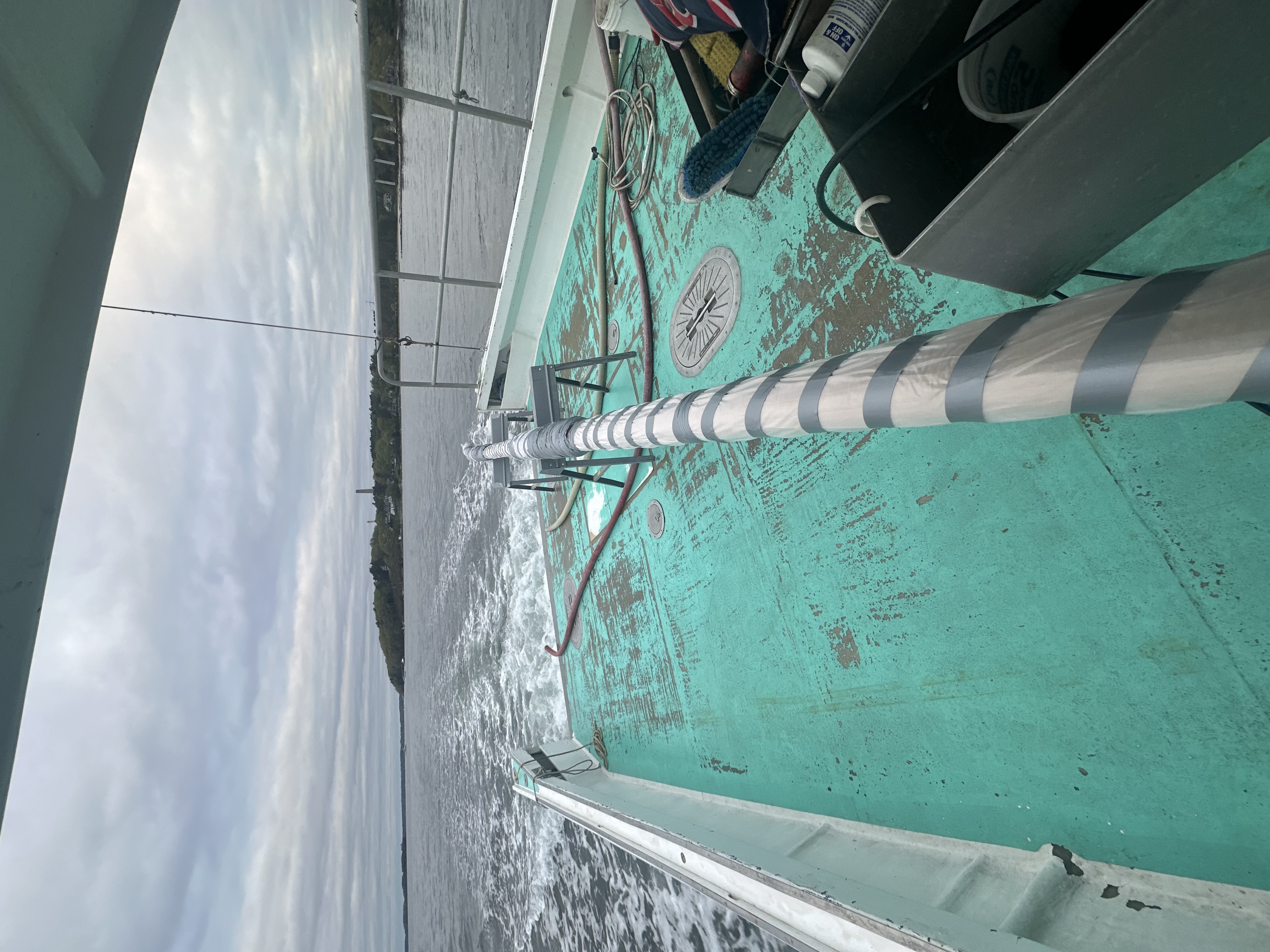
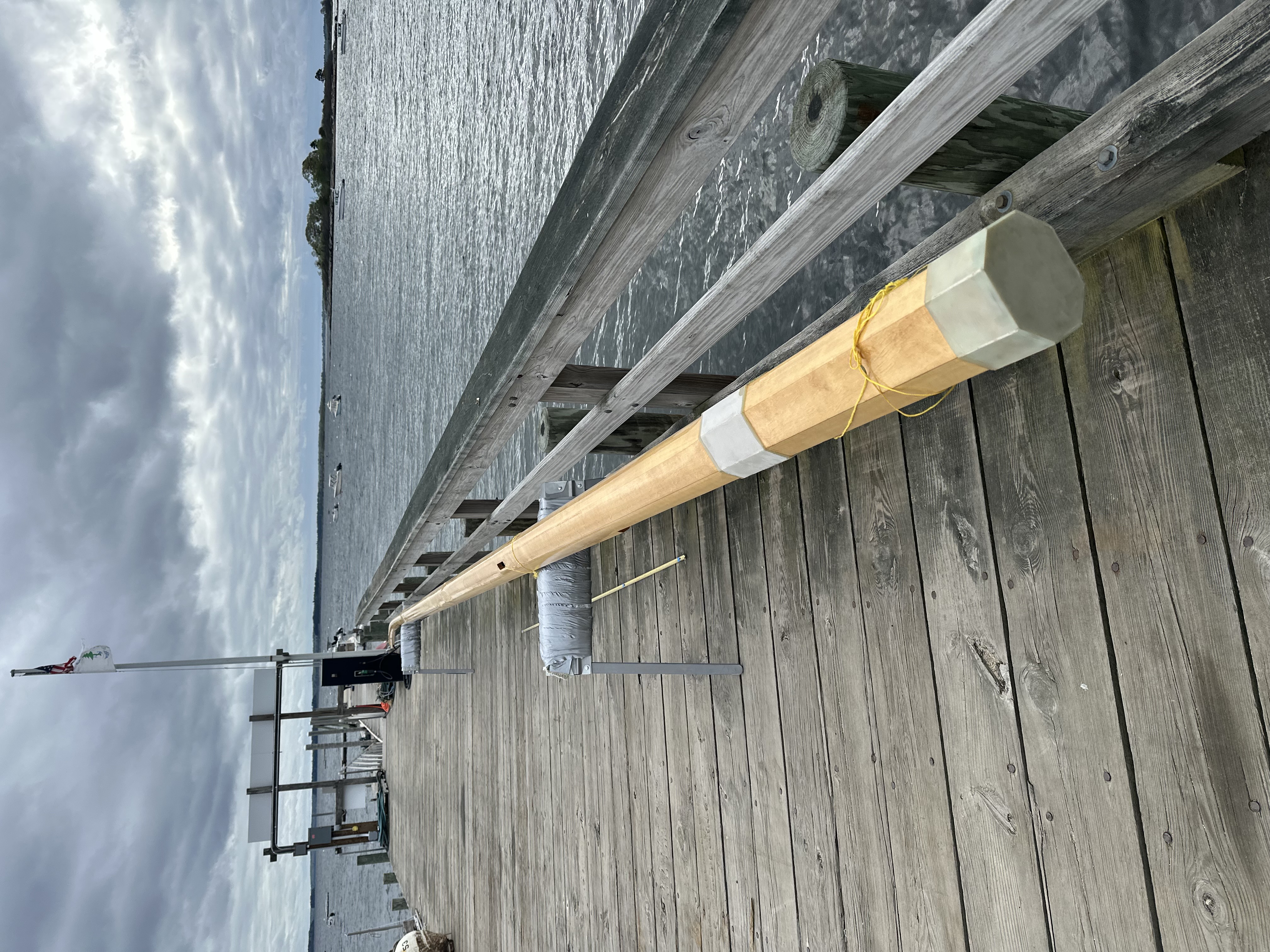
A walkaround of the faired spar — shaped, sanded, and ready for hardware and varnish. The taper runs clean from butt to masthead, and the mast weighs less than a hundred pounds.

Australian Shepherd sitting in the workshop
Shop foreman.
Boots covered in spruce dust after sanding
The aftermath from an evening of spar sanding.

Hardware and rigging

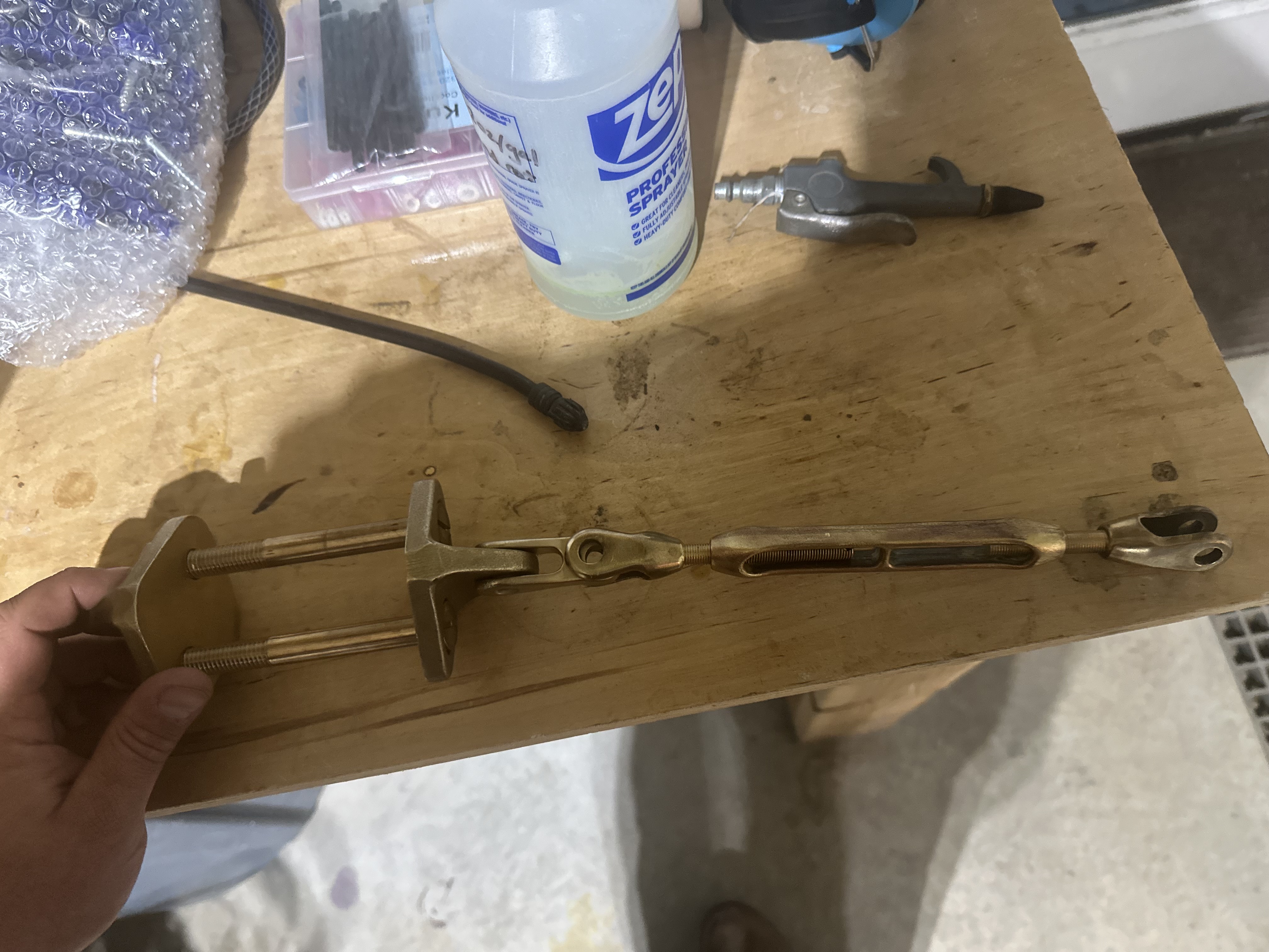
For the standing rigging, we made a decision early on: synthetic fiber instead of wire. Synthetic rigging — typically Dyneema or similar high-modulus polyethylene — is dramatically lighter than stainless steel wire, doesn’t corrode, and can be spliced by hand without a swaging machine. We had experience building and splicing our own rigging for International 14 skiffs, which are small high-performance racing dinghies. The I14 world has been running synthetic rigging for years, and we’d built enough confidence in the material to bring it to Ariadne.

Presentation about synthetic rigging for classic boats
"The Virtues of Synthetic Rigging" — a presentation by Ian Weedman and Jen Bates from Brion Toss Rigging. The case for synthetic on classic boats: lighter, no corrosion, and field-serviceable with basic tools.

The one concern with synthetic rigging is pre-stretch. When you first tension a new set of shrouds, the splices settle under load — the fibers in the splice tails bed into each other and the whole assembly elongates slightly. It looks like creep, but it’s not the fiber stretching — it’s the joints finding their final geometry. If you don’t account for this by pre-stretching the rigging before final installation, you’ll be sad when the splices settle. We’ll cover the shroud fabrication and pre-stretch process in a later post.

Whiteboard showing complete standing rigging plan
The whiteboard rigging plan. The complete standing rigging layout from masthead to chainplates, with a parts list: thimbles, toggles, turnbuckles, spreader tips, brackets, and shroud tangs.
Hand-drawn sketch of spreader bracket design options
Design sketches for the spreader brackets. Bronze or stainless? Mechanical attachment or welded? Every piece of hardware on the spar needs a plan before the wood is shaped.

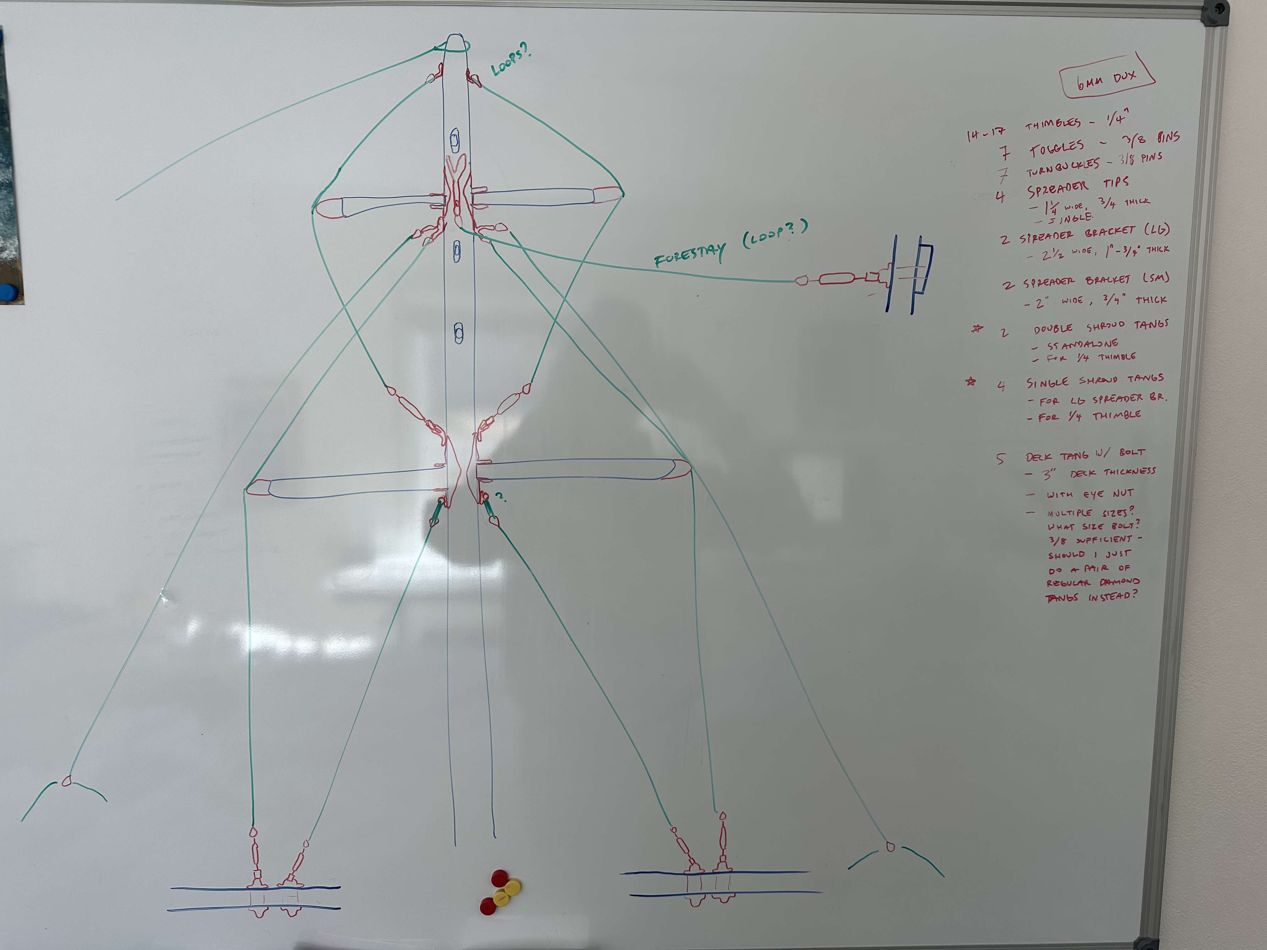
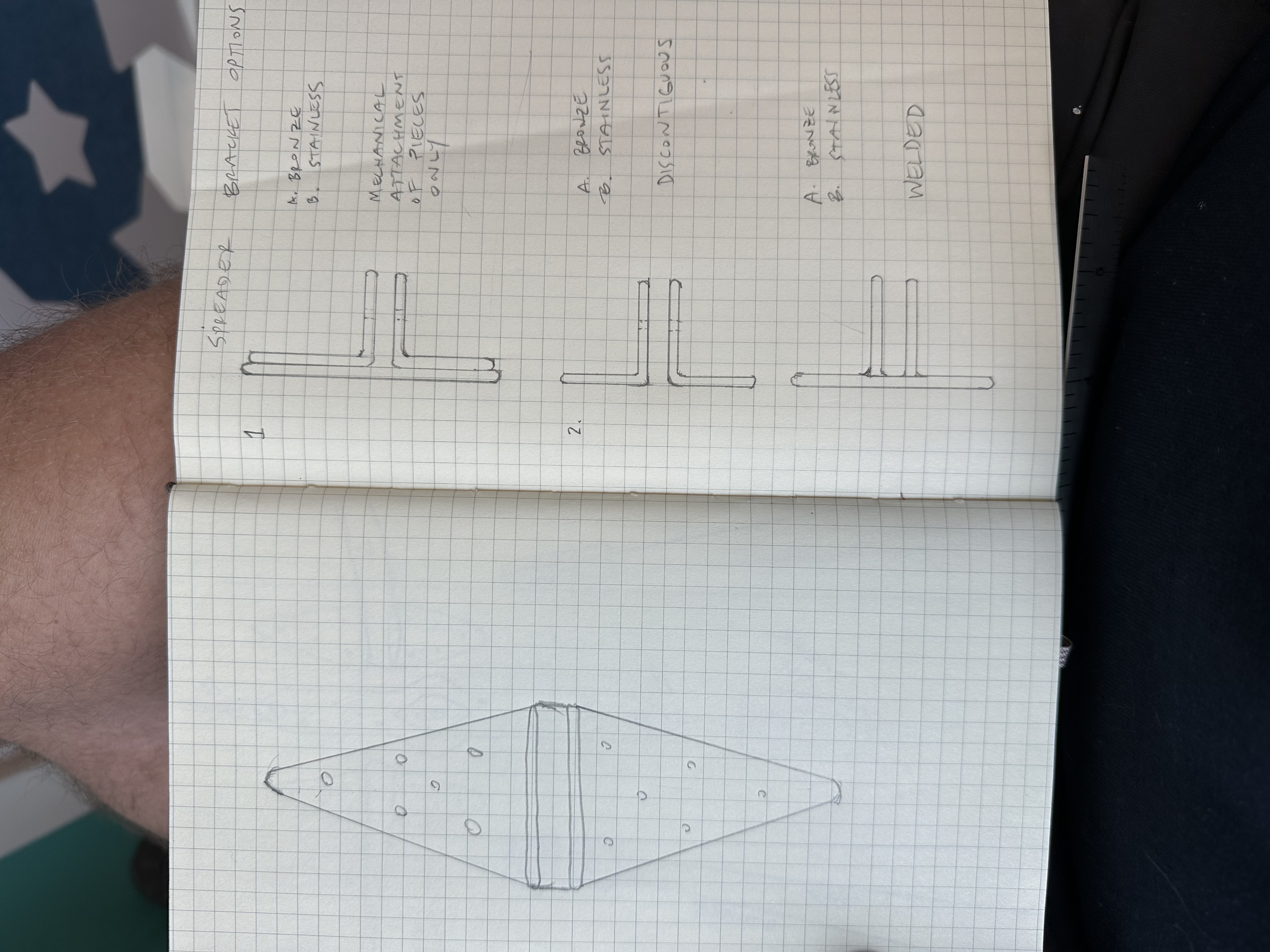
We went all bronze for the mast hardware — tangs, bolts, brackets. Bronze is more expensive than stainless but doesn’t corrode in contact with salt water the way stainless can when it’s deprived of oxygen (crevice corrosion is what kills stainless on boats). Aloft, where weight matters most, we used composite tangs and looped halyard ends, as well as aluminum-composite sheaves for halyard exits.

Working with bronze sheet turned out to be a bit of its own education. We needed 90-degree bends for the spreader brackets and dogleg bends for the shroud tangs. We wanted silicon bronze — the gold standard for marine hardware — but couldn’t find it in half-hard or annealed temper. What we could get was phosphor bronze, which is harder and less pliable, but still marketed as bendable. We learned, however, that phosphor bronze in full-hard temper doesn’t want to take a sharp bend without cracking. We decide it was OK to get around this with annealing: heating the metal to just below cherry red (turn the lights off!) and working it while hot. But you have to anneal before every major bend, and clean it up afterwards, which is a bit annoying.

Phosphor bronze sheet cracked during bending
Without annealing. Phosphor bronze sheet broke at the bend line.
Bronze fitting showing heat discoloration from annealing
A bronze fitting after annealing and bending. This would be half of a termination assembly aloft for a shroud. The heat discoloration is from the torch — the piece gets brought to below cherry red and bent.
Bronze cylindrical sleeve or cap piece
Testing a 180 degree tight bend. No problem.
Bronze masthead fittings and tang plates laid out on workbench
All the spreader brackets.
Bronze turnbuckle and tang assembly for shroud attachment
The turnbuckle and tang assembly that secures the shrouds to the deck. The bolts between the tangs pass through a spreader bar under the deck, and the lower tang routes shroud tension down to the mast step — consolidating rig loads into the backbone.
Hand-drawn hull cross-section showing structural load paths
A cross-section sketch of the hull structure showing how shroud loads transfer from the mast through the spreader bar, down past the mast step, and into the keel. The rigging doesn't just hold the mast up — it ties the whole boat together.

The finished spar

The new mast weighs less than hundred pounds, is built to the class rule, the jumper strut is gone - and it’s actually strong! Major upgrade. Then we had to lug it out to Maine.

Mast on an extended trailer for transport
Forty feet of mast on the trailer. A welder friend extended the trailer by about 25 feet to accommodate the spar.
New mast being transported on the back of a lobsterboat
The mast riding out to the island on the back of a friend's lobsterboat. Big boat.
Finished spruce mast lying on a dock
The finished spar on the dock.
First test fit of the mainsail on the new mast at the boatyard
First test fit of the mainsail that came with the boat, with the mast on sawhorses at the boatyard. A bolted Cheeky Tang is visible near the headboard.
Close-up of mainsail hoisted on new mast
The mainsail on the new spar. The sail, like the mast, dates to a different era — but it fit suprisingly well.

Building a mast is an accumulation of small decisions that add up to a single piece that you must trust deeply. The old spar served Ariadne well for ninety years. We’d like this one to do the same.