Next set of structural boat work: frames, hanging knees, and floor timbers. These are pieces that tie everything together — frames tie planks to each other, floors tie planks to the backbone, and hanging knees tie the deck to the hull.
This post covers the interior structural work in Ariadne’s cockpit area. We fabricated a new set of laminated frames, hanging knees to support the side decks, and cockpit floor timbers that had to be fitted around existing keel bolts with their tops co-planar to carry the cockpit sole.
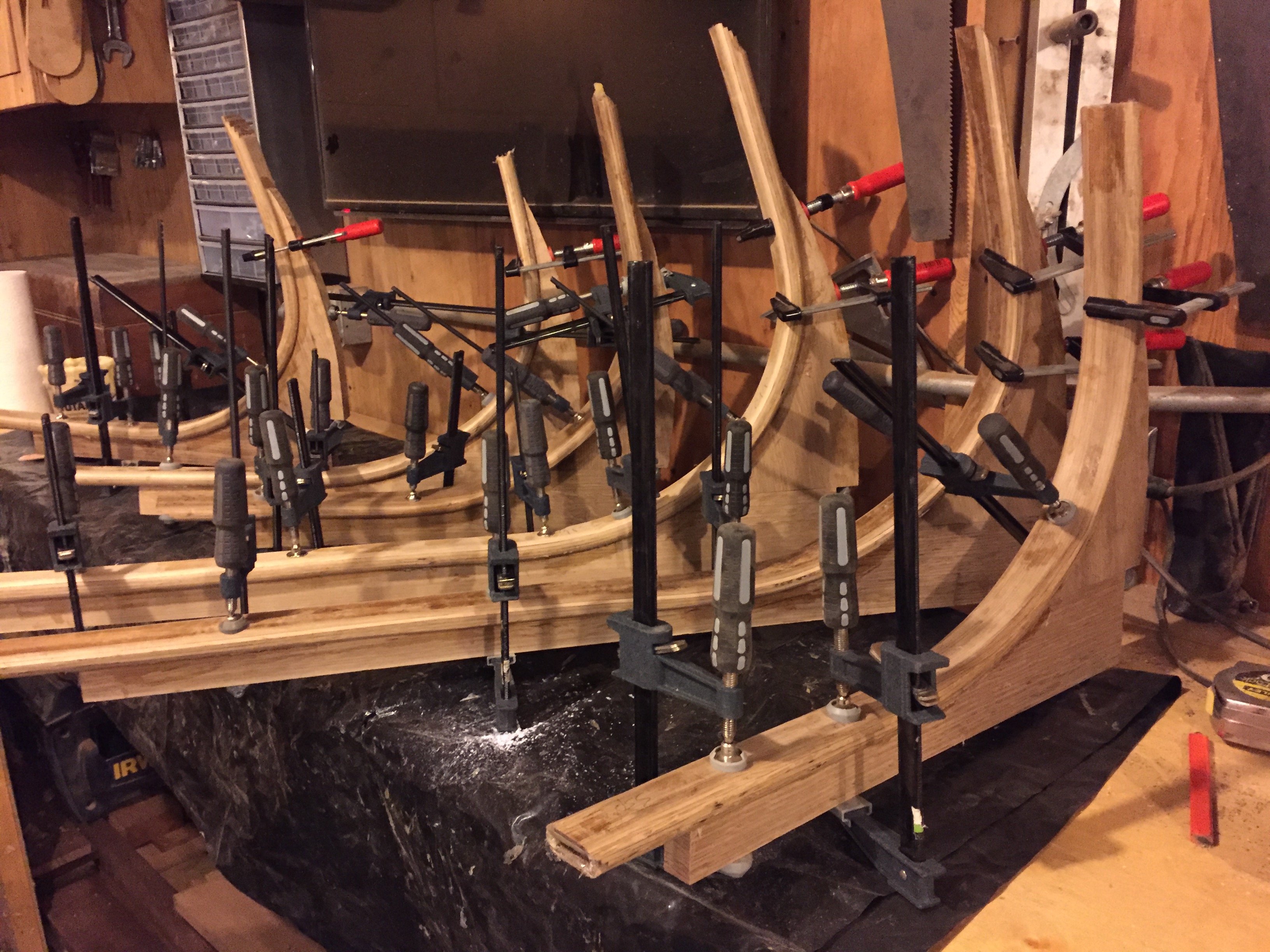
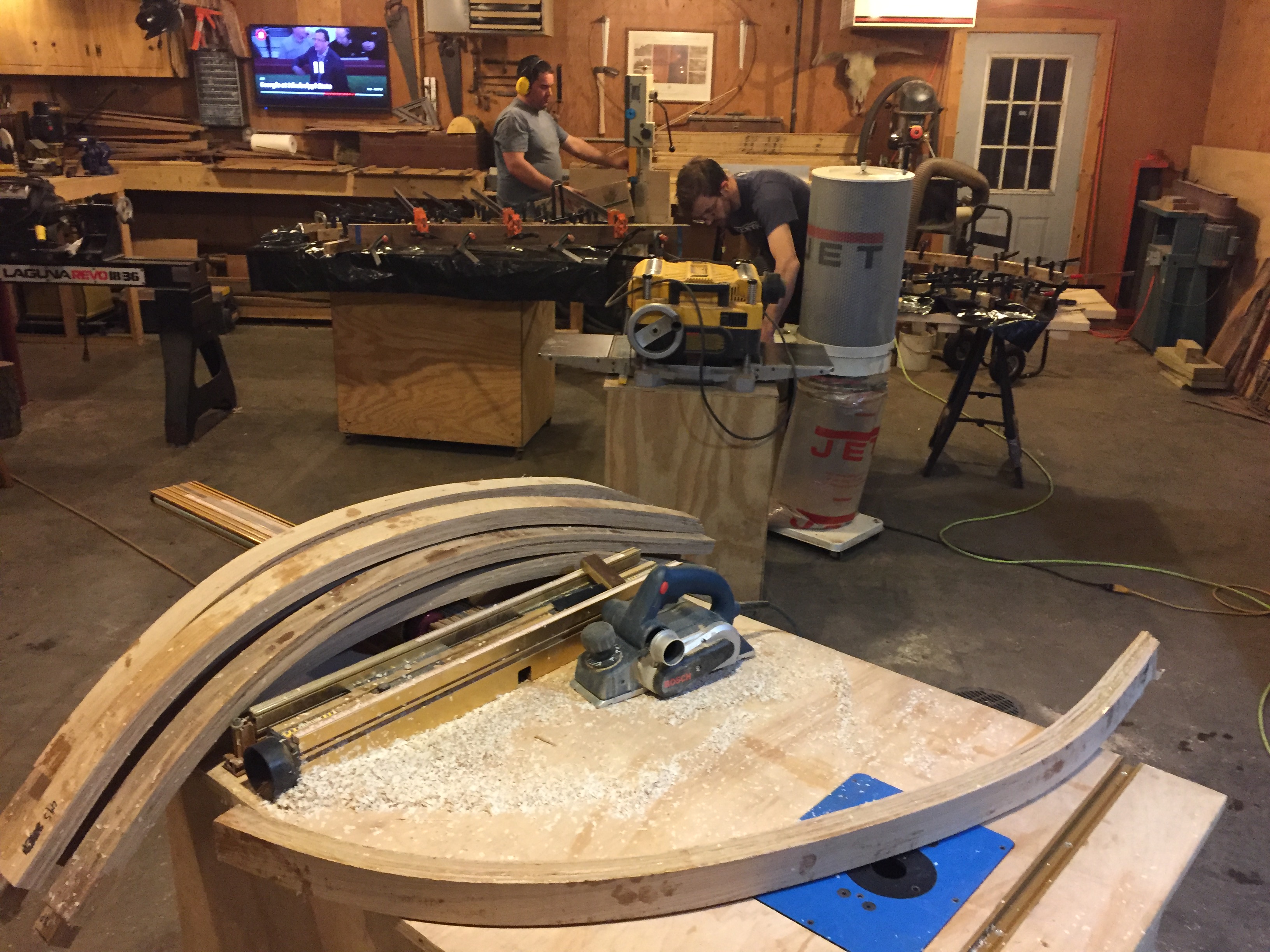
Laminated frames
We’d laminated frames before for the forward sections, so the process was familiar. Thin strips of white oak are glued up over a form with epoxy, clamped until cured, then removed and beveled to fit. The form is a critical piece — it defines the hull shape at each station, and the shape differs for every frame. By screwing blocks to a plywood strongback with all station lines marked, we could create form shapes as needed and glue up the frame blanks in batches.


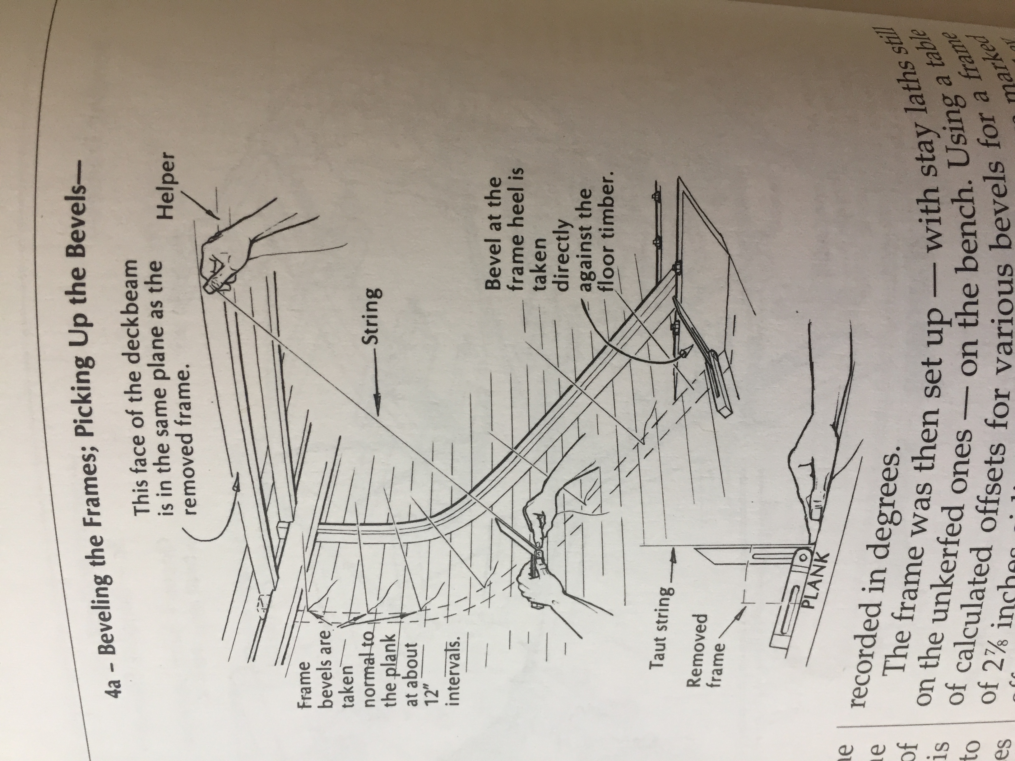
Picking up bevels
With laminted frames like these, the outside faces also had to be beveled to sit flush against the inside of the planking. The hull is a compound curve, so the bevel angle changes continuously along the length of each frame. Getting this wrong means a frame that only contacts the planking at a few high points instead of bearing evenly along its full length.
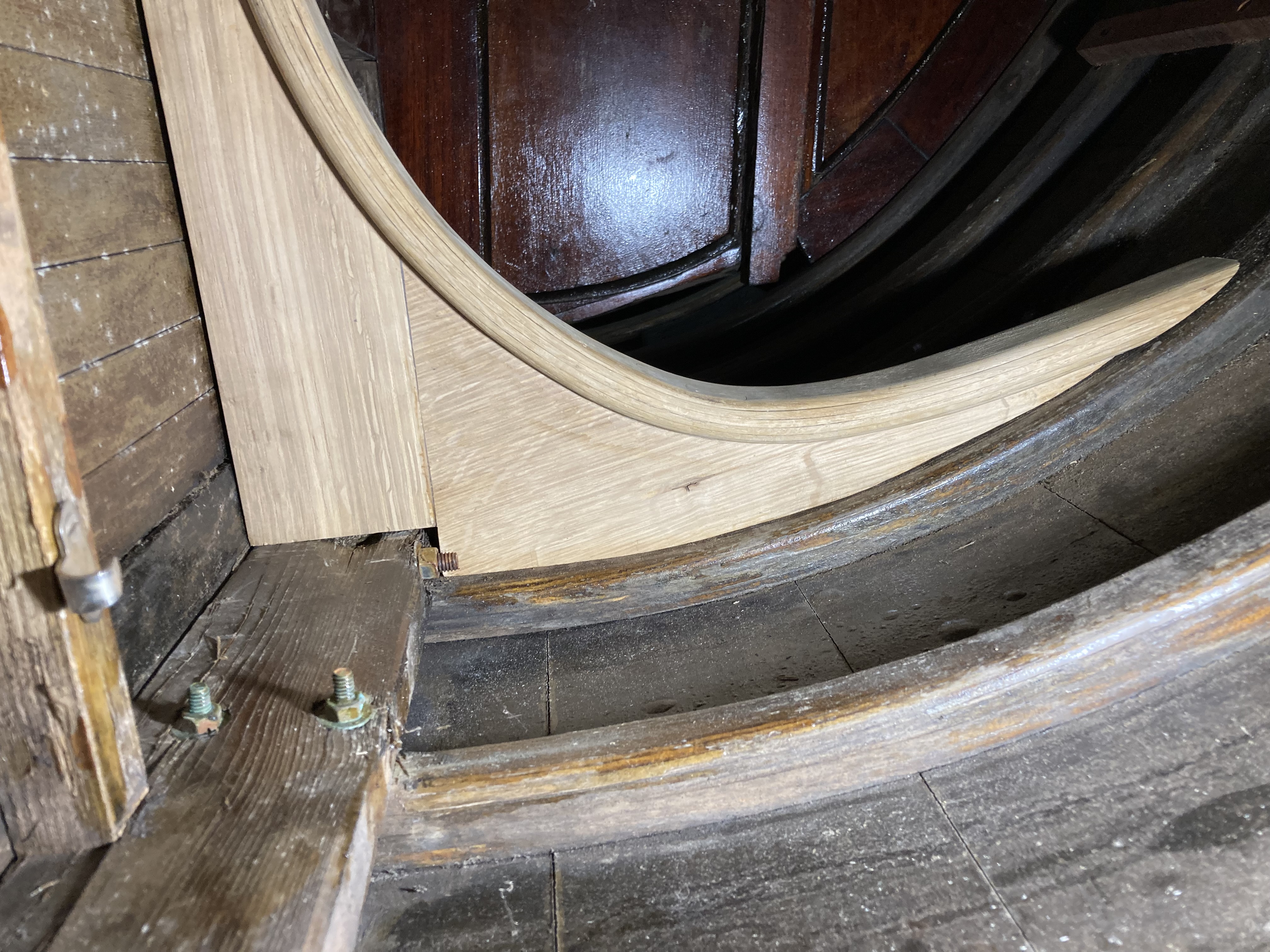
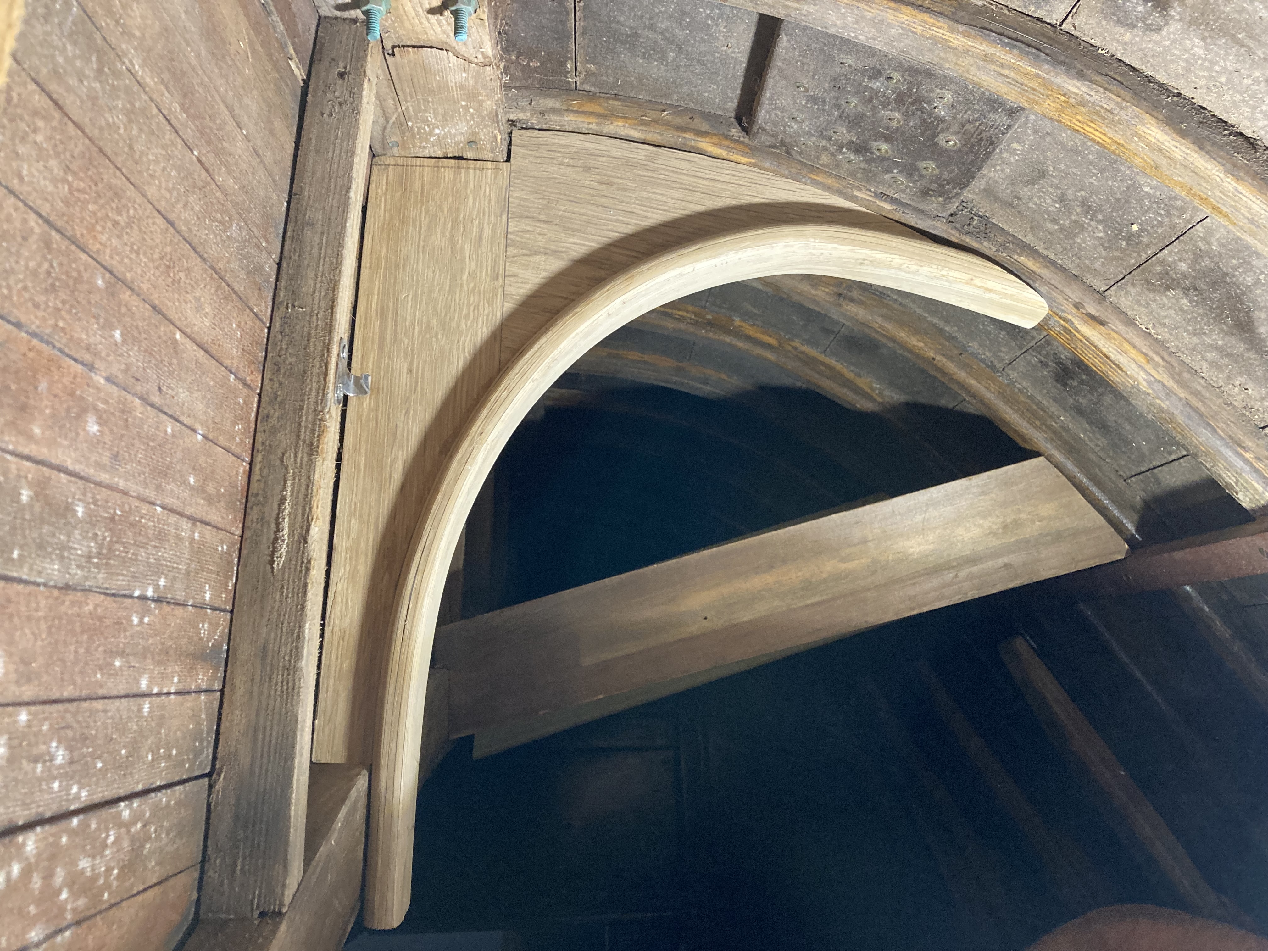
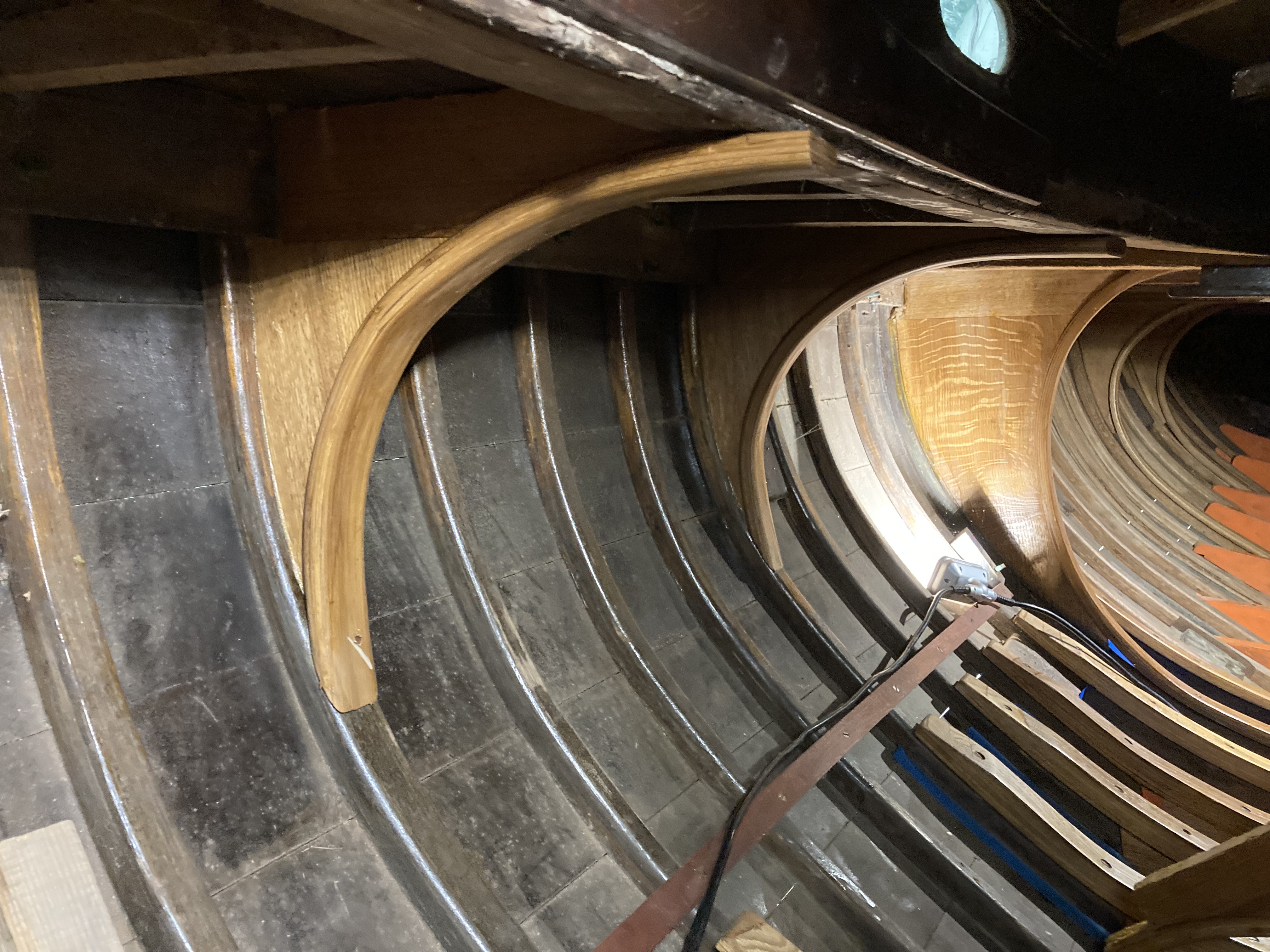
Hanging knees
Hanging knees are the brackets that connect the deck beams to the hull sides. They transfer loads between the deck and the hull structure — everything from the weight of someone standing on deck to the shock of slamming into a wave to the torsional loads produced by heeling and righting moment. A knee that’s too small or poorly fitted is a structural weak point.
In the old days (and to some extent now, when timber is available) boatbuilders would saw knees out of “grown crooks” - brace roots or branches with a sharp 90 degree curve that matches the hull to deck joint. You need to be careful to minimize grain runout so the knee doesn’t split at the fasteners. We laminated two pieces of oak with perpendicular grain, then finished up with a laminated “ring” around the exterior of the knee.
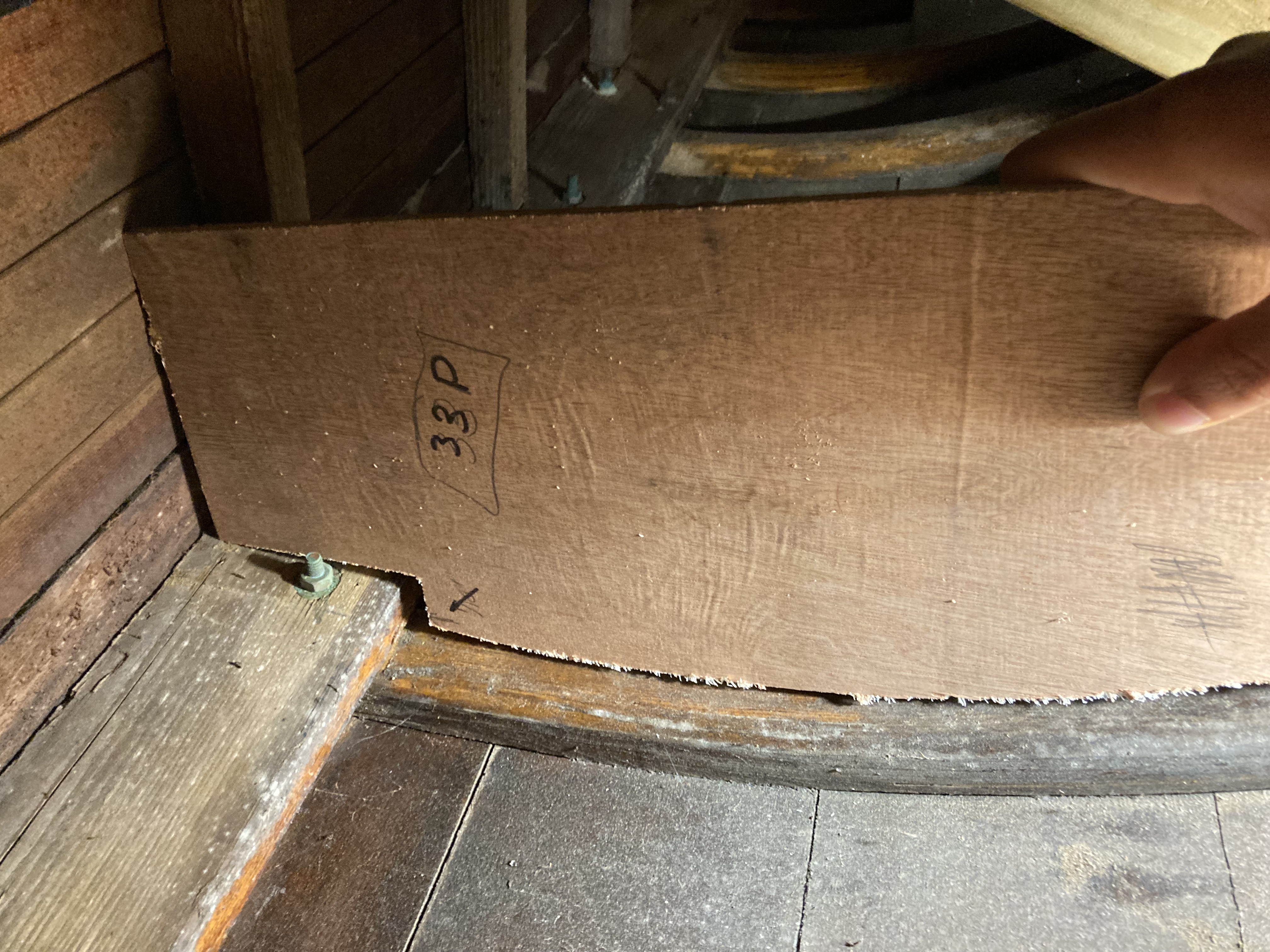
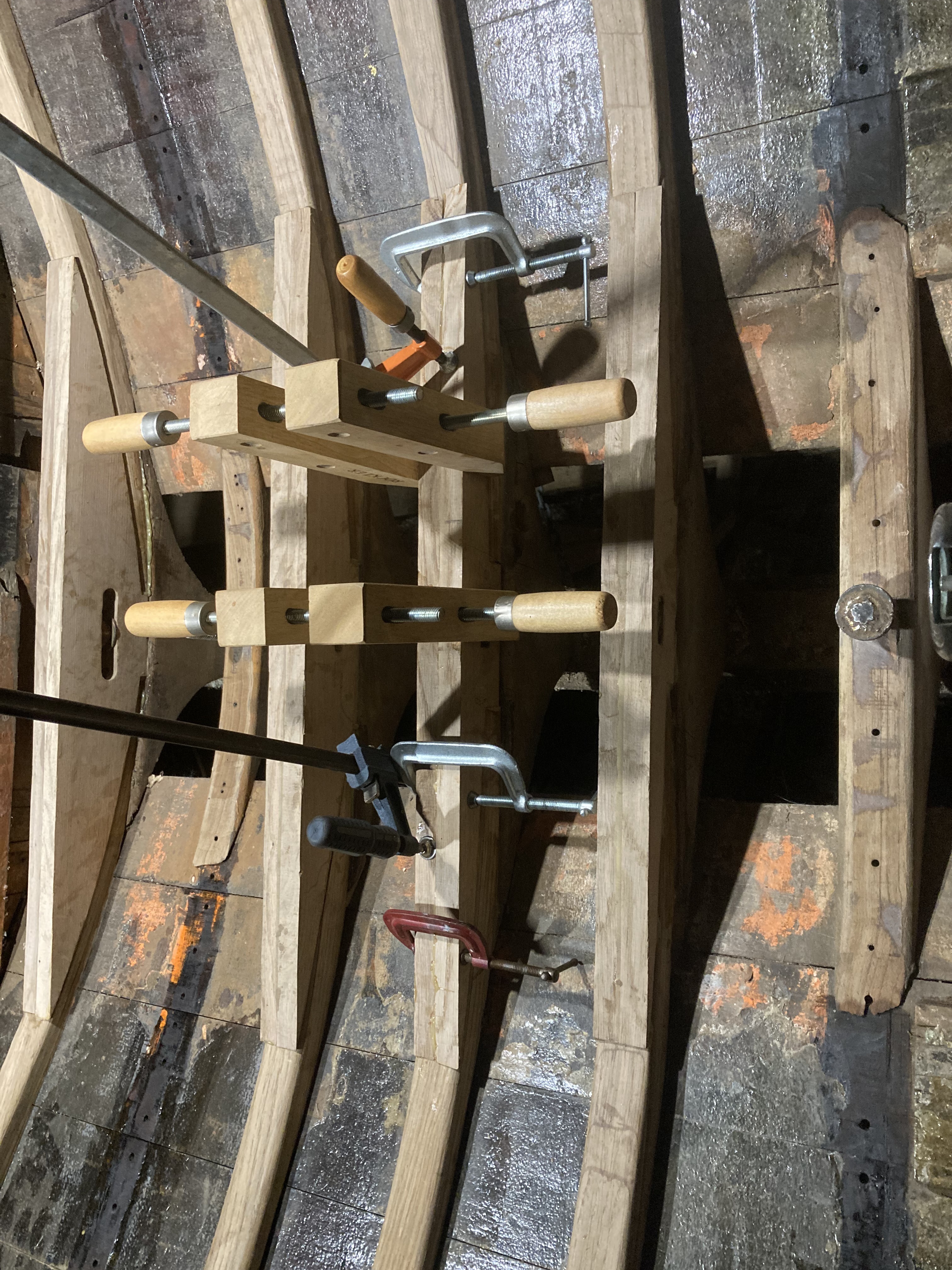
Cockpit floor timbers
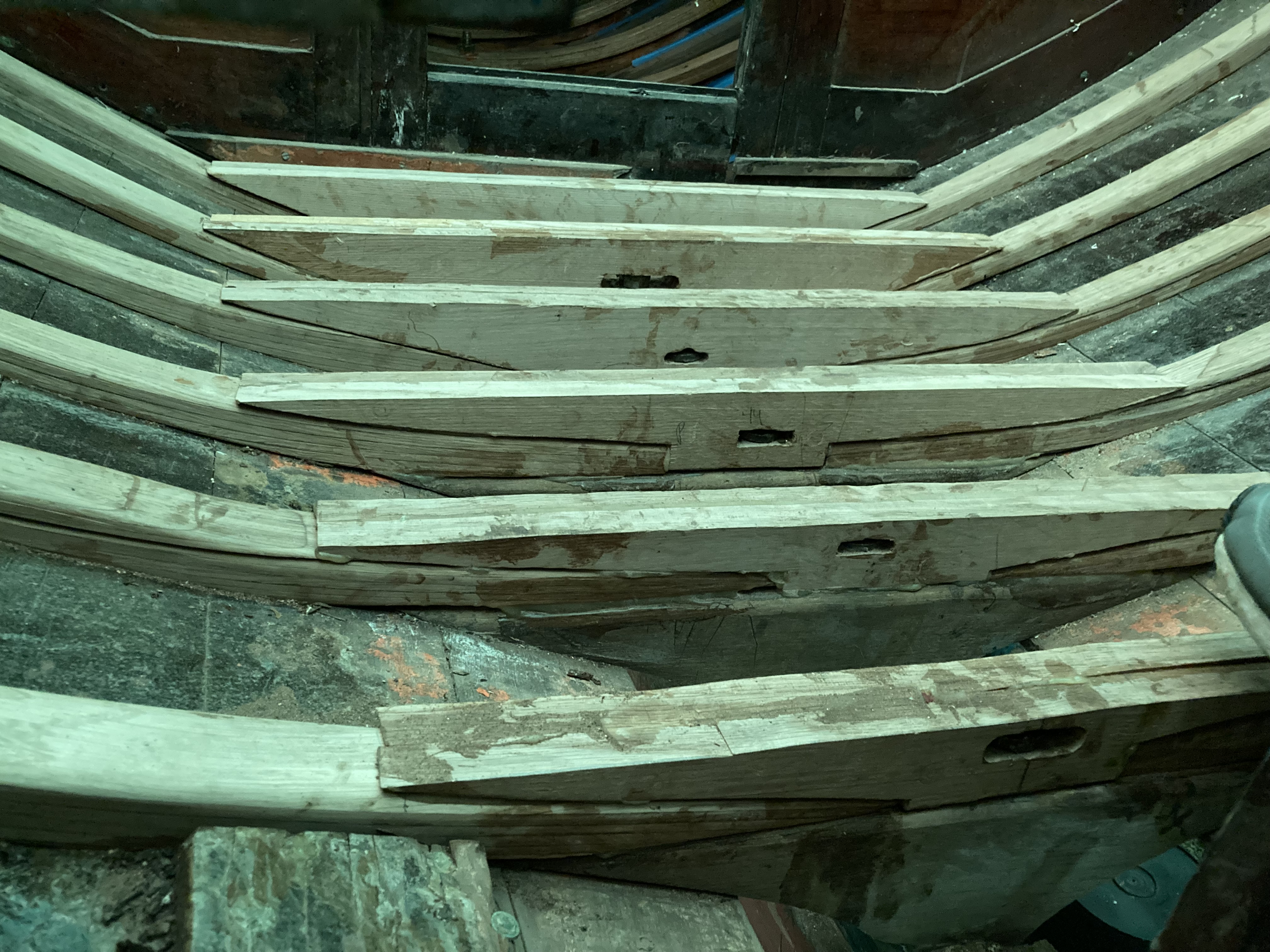
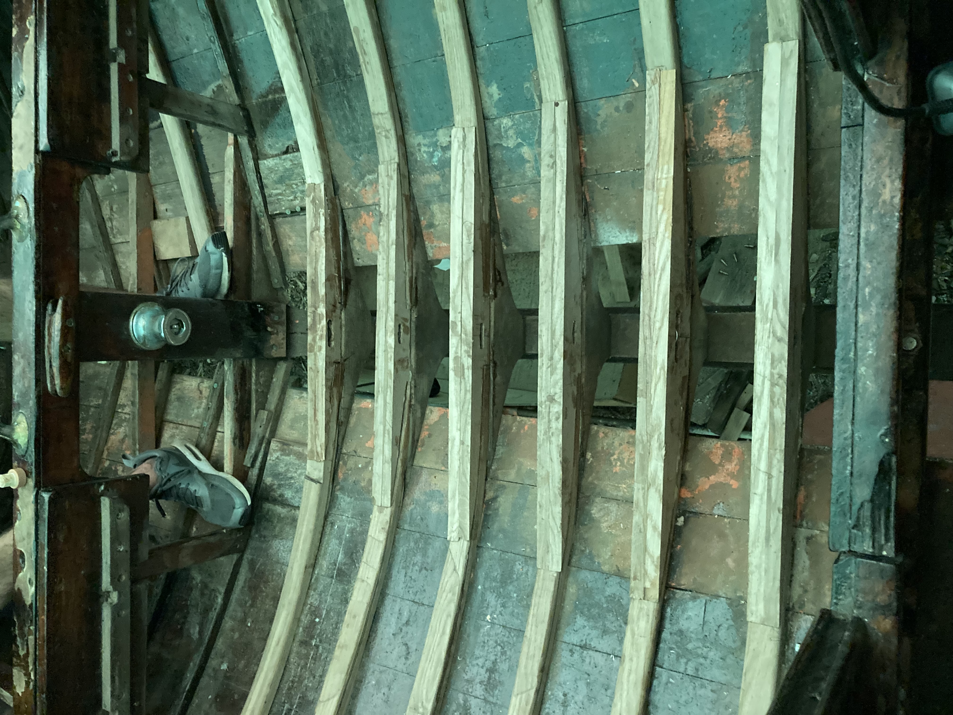
Floor timbers run athwartships across the top of the keel, tying the two halves of the hull together at the garboards. In the cockpit, they also serve as the structural support for the cockpit sole, which means their top faces have to be perfectly co-planar. Any error would show up as a rocking or uneven sole.
The complication in this location is that each floor timber had to be fitted around existing keel bolts and their welded-on nuts that protruded through the top of the keel. Some floors are built in halves and glued up around the bolts with G-flex epoxy, with horizontal channels cut to clear the nuts. Every one is a custom piece: scribed to the hull shape on the bottom, beveled on the faces that bear against the planking, and leveled across the top.
None of this work will be visible when the boat is finished. The floor timbers will be hidden under the cockpit sole, the knees deep under the cabin house, the frames behind joinery. But it’s the structure that everything else depends on.