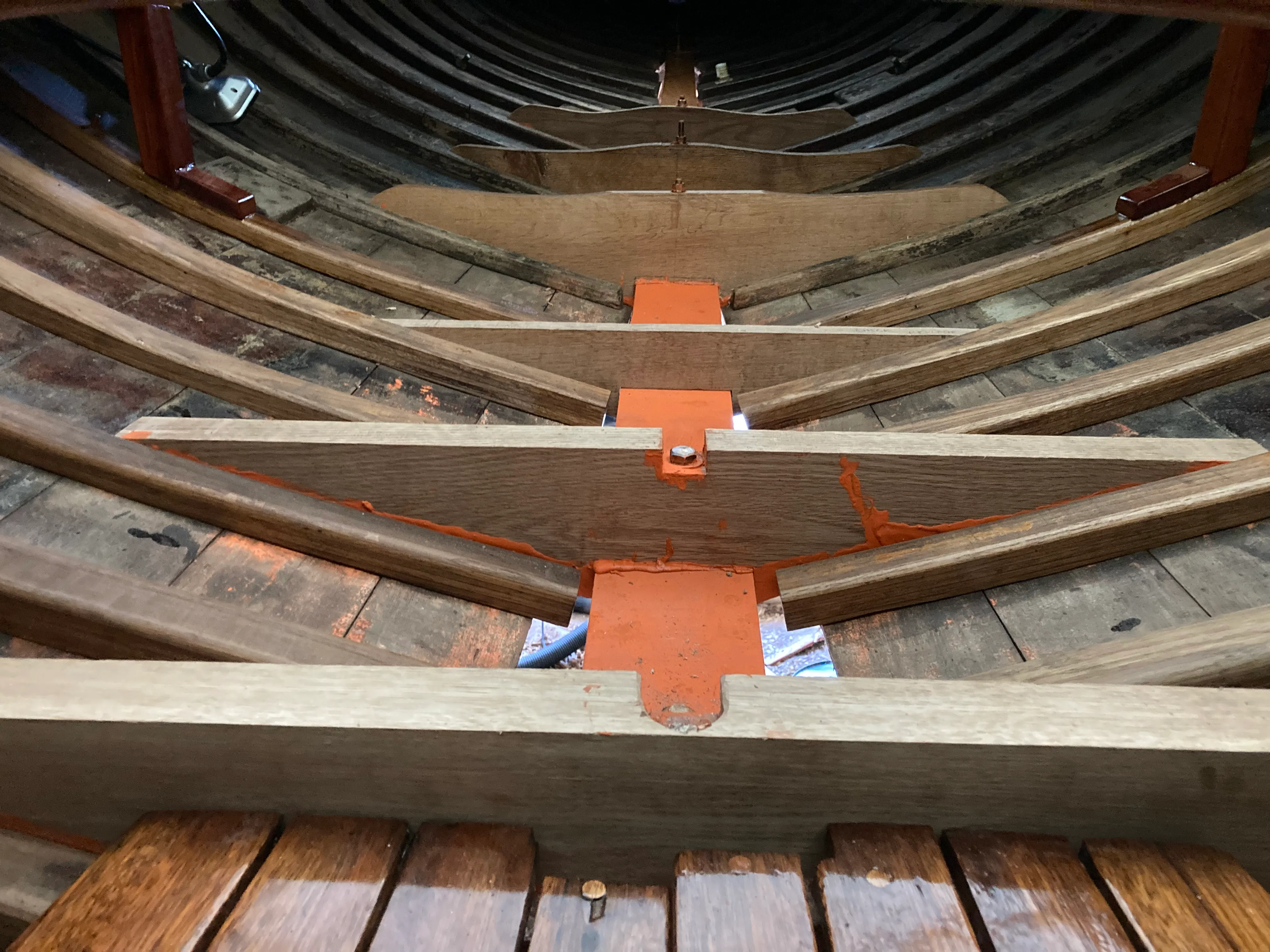
The biggest issue with restoring a wooden boat is managing mission creep. Like working on an old house, it’s difficult to avoid the following pattern:
- Identify a problem.
- Begin some form of demolition to address the problem.
- Discover something else that needs attention.
- Begin an additional semi-related project.
- Repeat.
This pattern is remedied in a similar way to managing a greenfield software development project. Even if you don’t have a complete understanding of the problems you might encounter, you can still (a) categorize and proactively estimate the uncertainty and severity of classes of issues you may face, and (b) stay focused on your ultimate objective when you’re deciding whether to expand your scope.
We had already suspected that there was some damage to an essential section of backbone timber that supports the long aft overhang and secures the rudder post. We discovered more problems as we repaired some planking in that area. Having done a replacement of a similar amount of centerline timber up forward, we were reticent to do it again - but decided that a rock-solid backbone was a top objective of our restoration and chose to proceed. Despite the fact that it would probably push our launch date back a year, given how infrequently we’re able to work on Ariadne.
Having come through the other side, I can say that it was the right choice. The old piece was in worse shape than we knew, and the replacement was very satisfying to shape and install.
Demo day
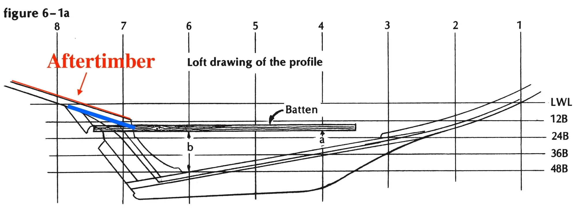
The first step was to remove the old aftertimber. Unlike the forefoot up forward, where we were able to release plank ends and drop the old forefoot out from the bottom, we needed to lift the old aftertimber out from above. This is because of how the pieces are joined together - the aftertimber has about 3’ of overlap with the keel timber at the forward end, which would have prevented the aftertimber from being removed from below:
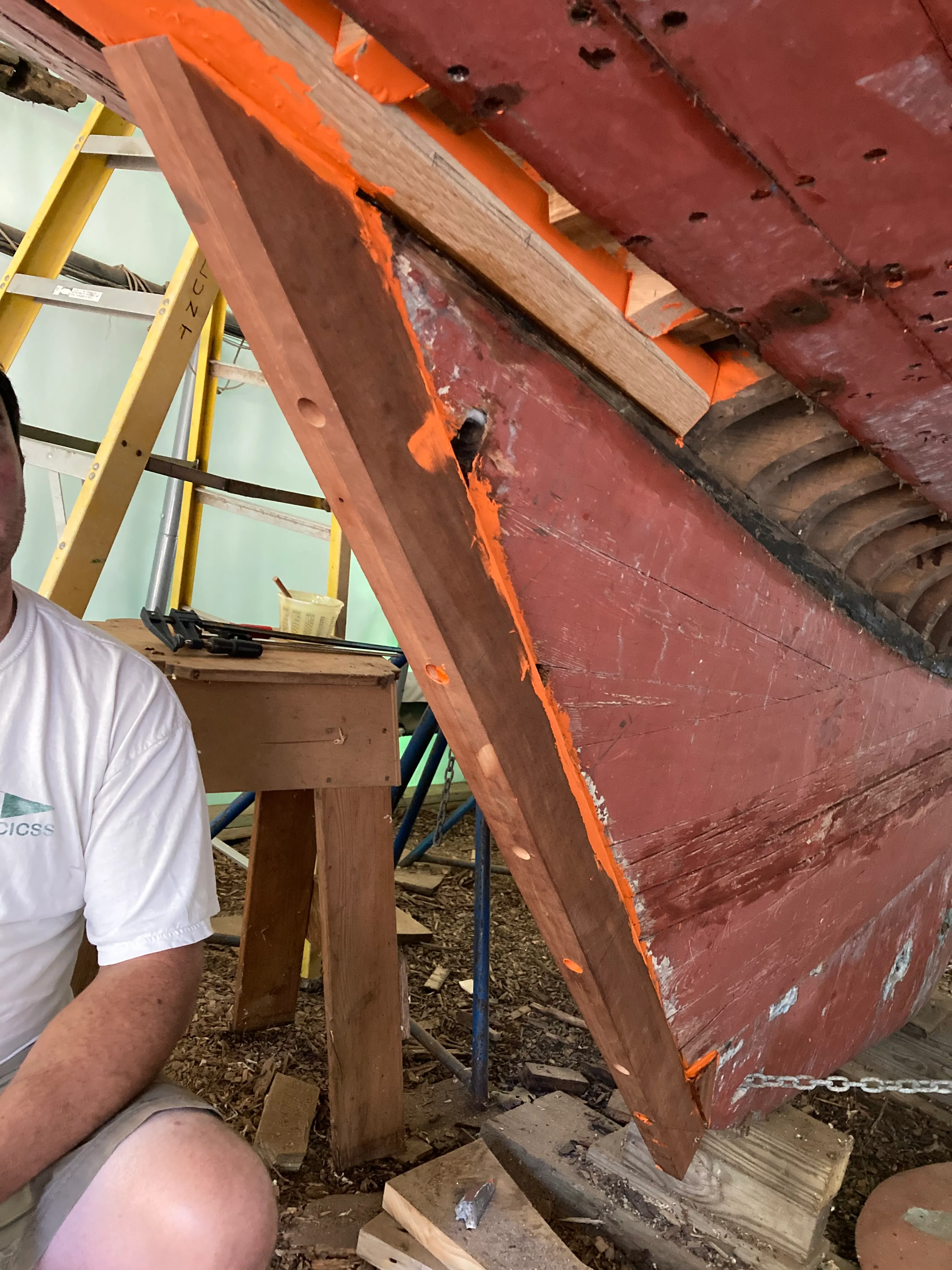
Before removing this section of timber, we had to construct a temporary support structure to keep the boat true to her shape. This was made by creating external “reverse floor timbers” that tie the port and starboard frames and planking together, just like regular floor timbers do. We then tied the reverse floors together with a beam of three 2x10s we screwed together. We just kind of made this up, but it worked very well.
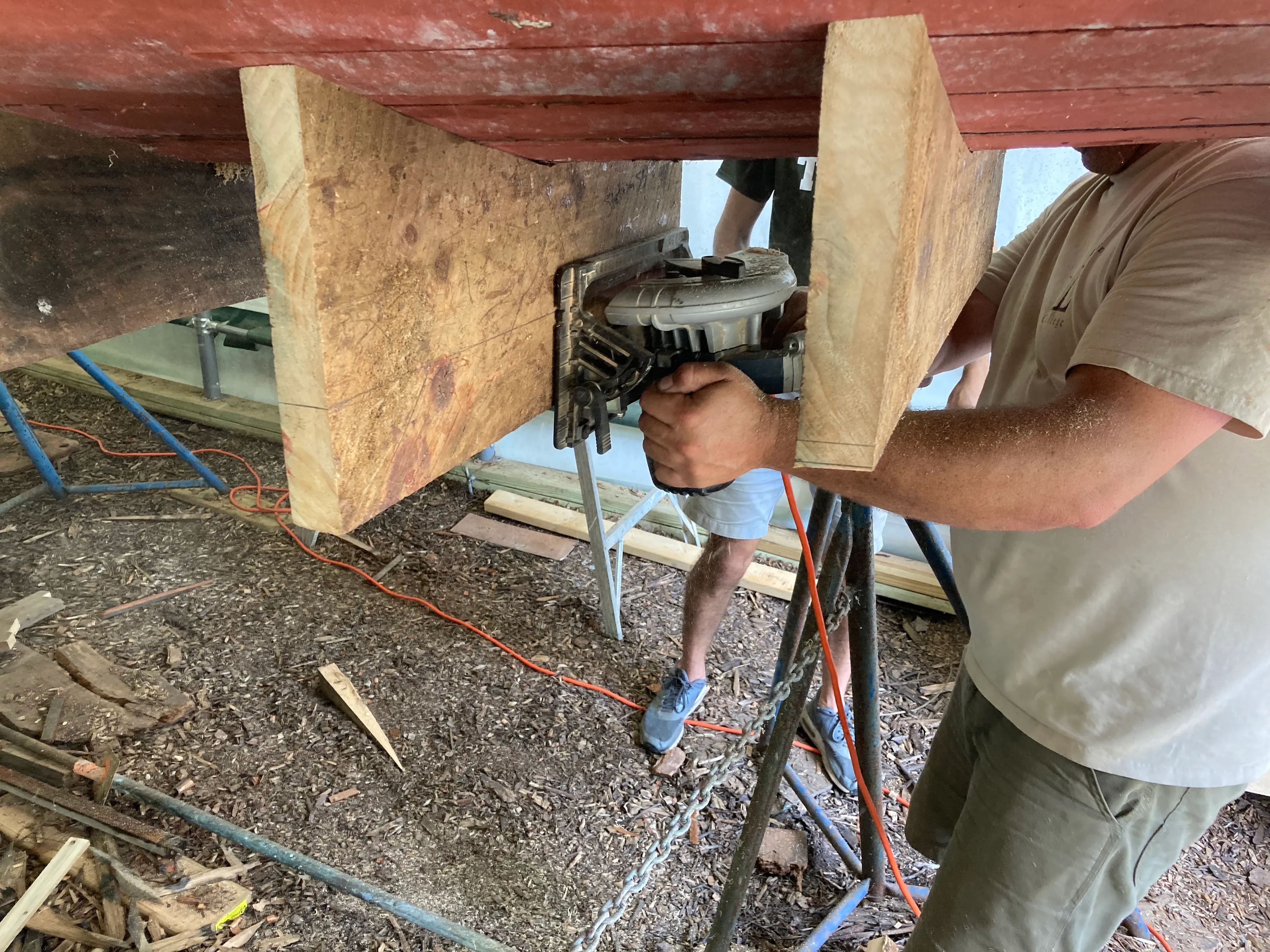
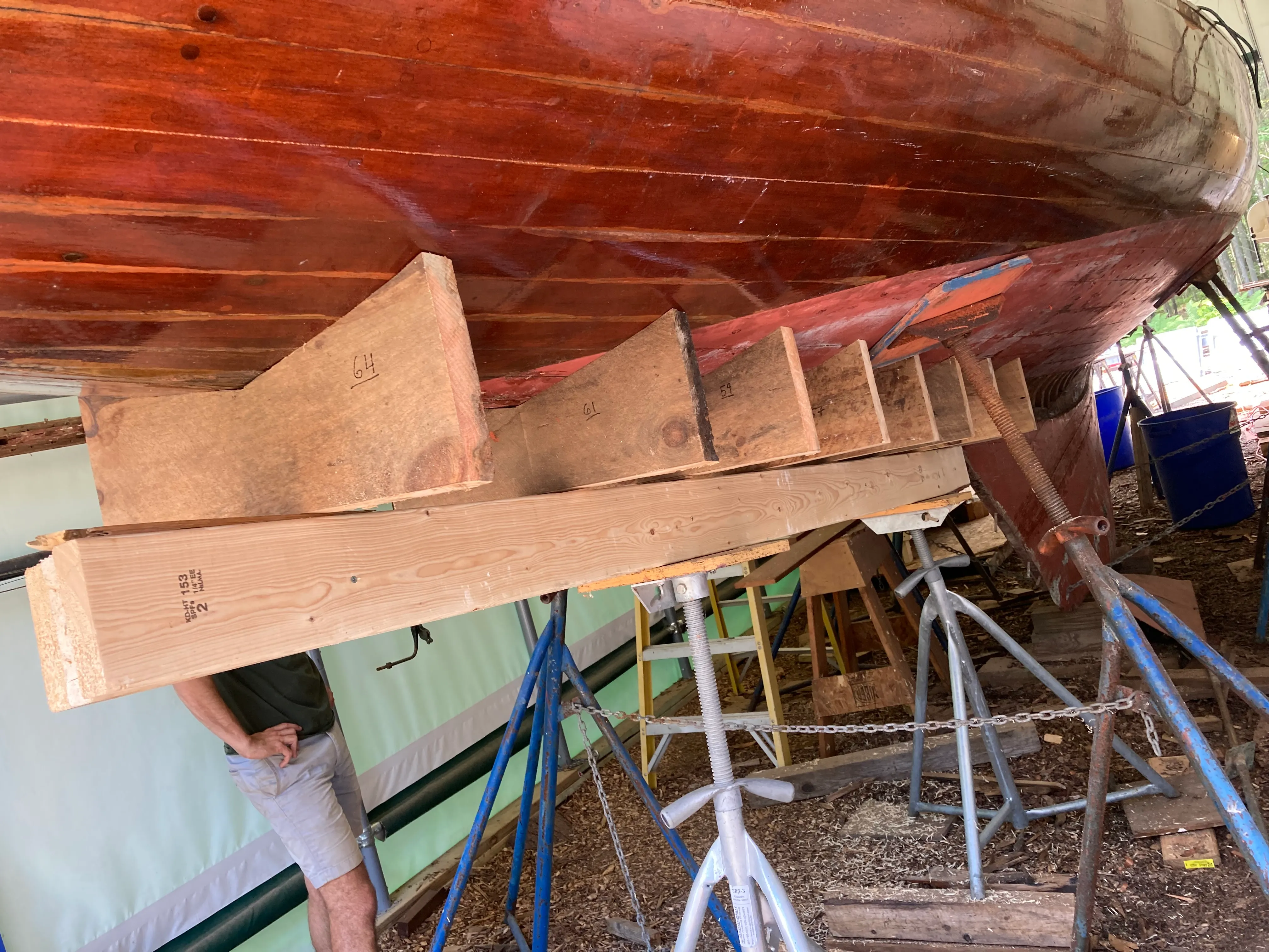
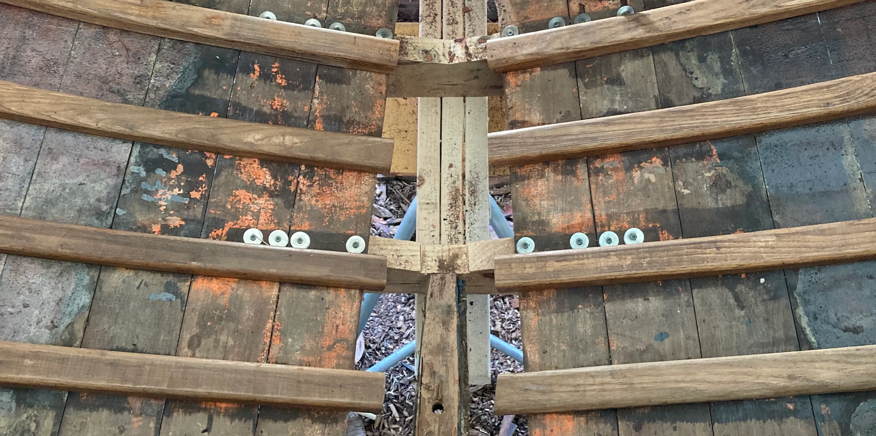
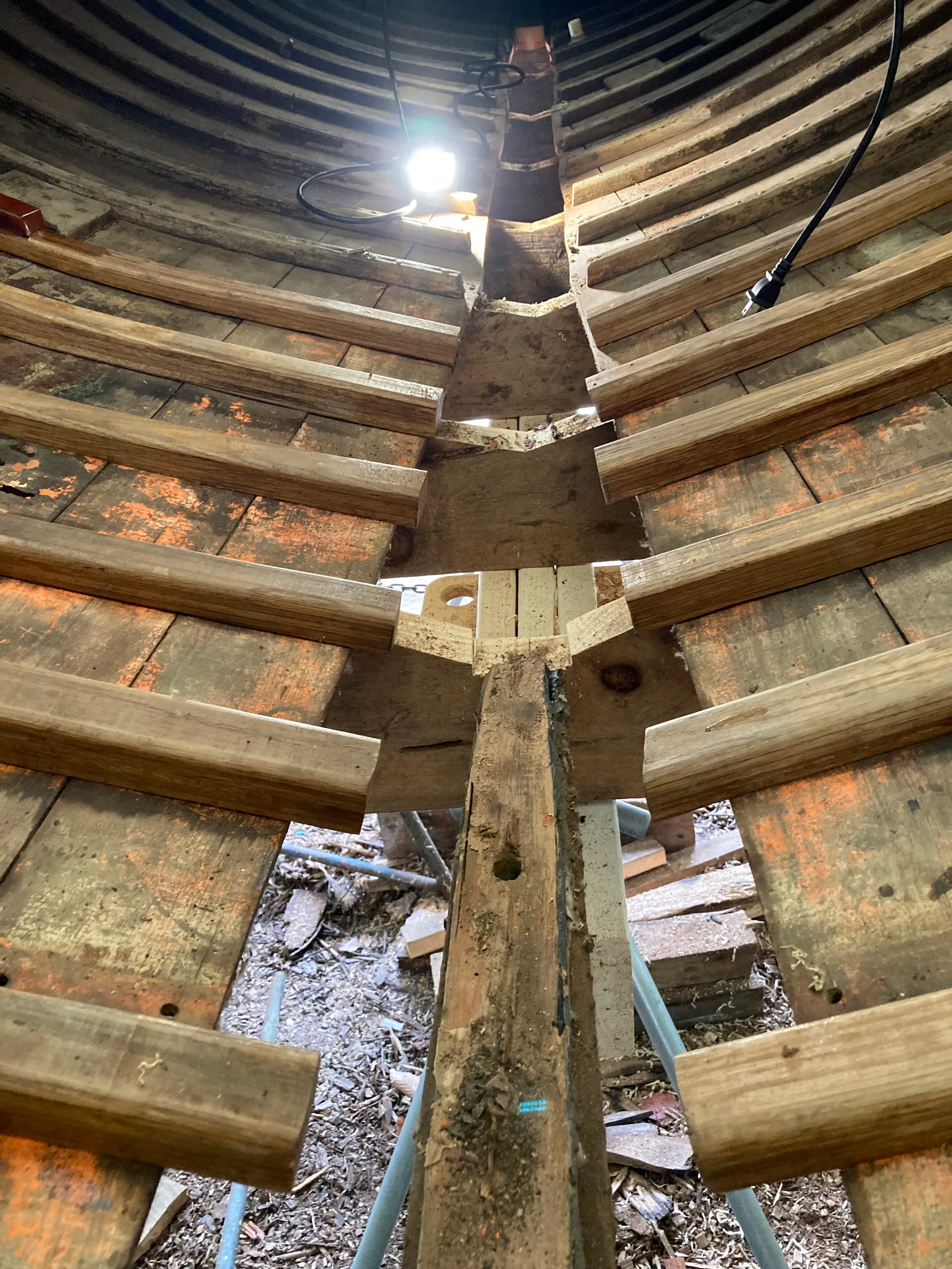
After the beam was in place, cutting away and removing the old aftertimber was straightforward. The planking in this area was already in poor condition and some had been removed, which gave us plenty of room to unbolt the old aftertimber from the keel timber at the forward end and crosscut at the aft end. We needed to be careful to leave enough material at the aft end to allow for cutting a 12:1 scarf joint.
Measuring and marking
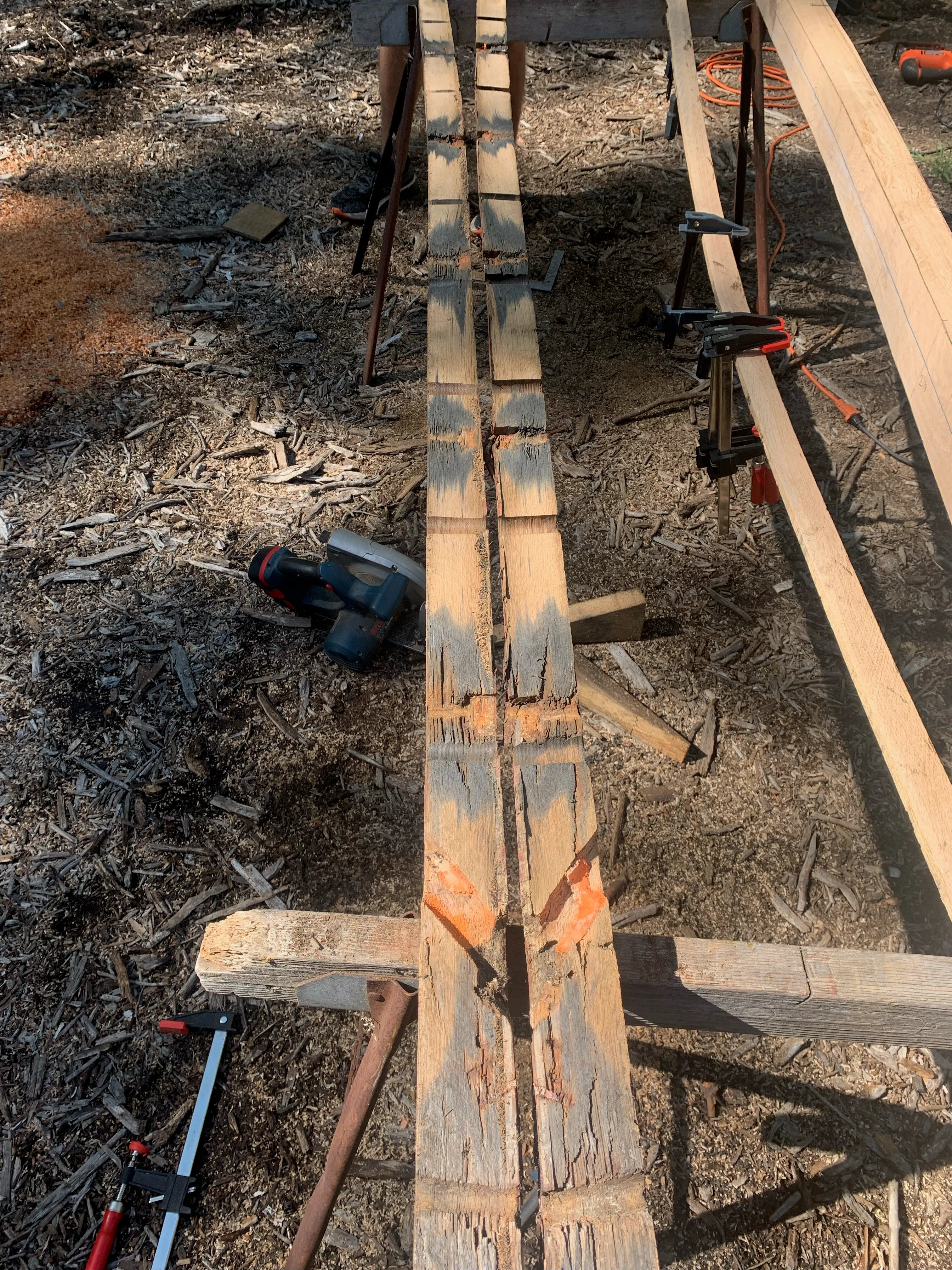
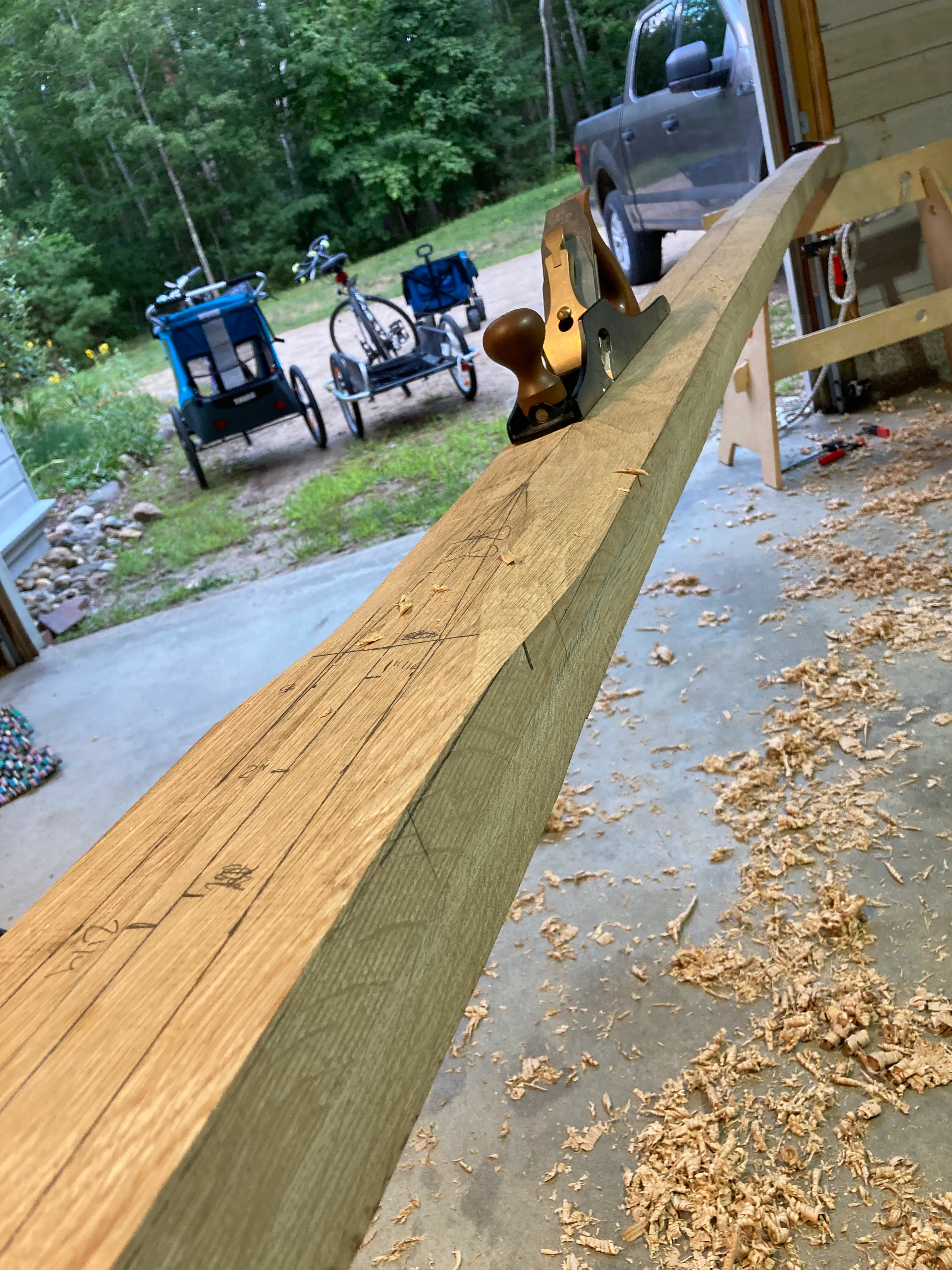
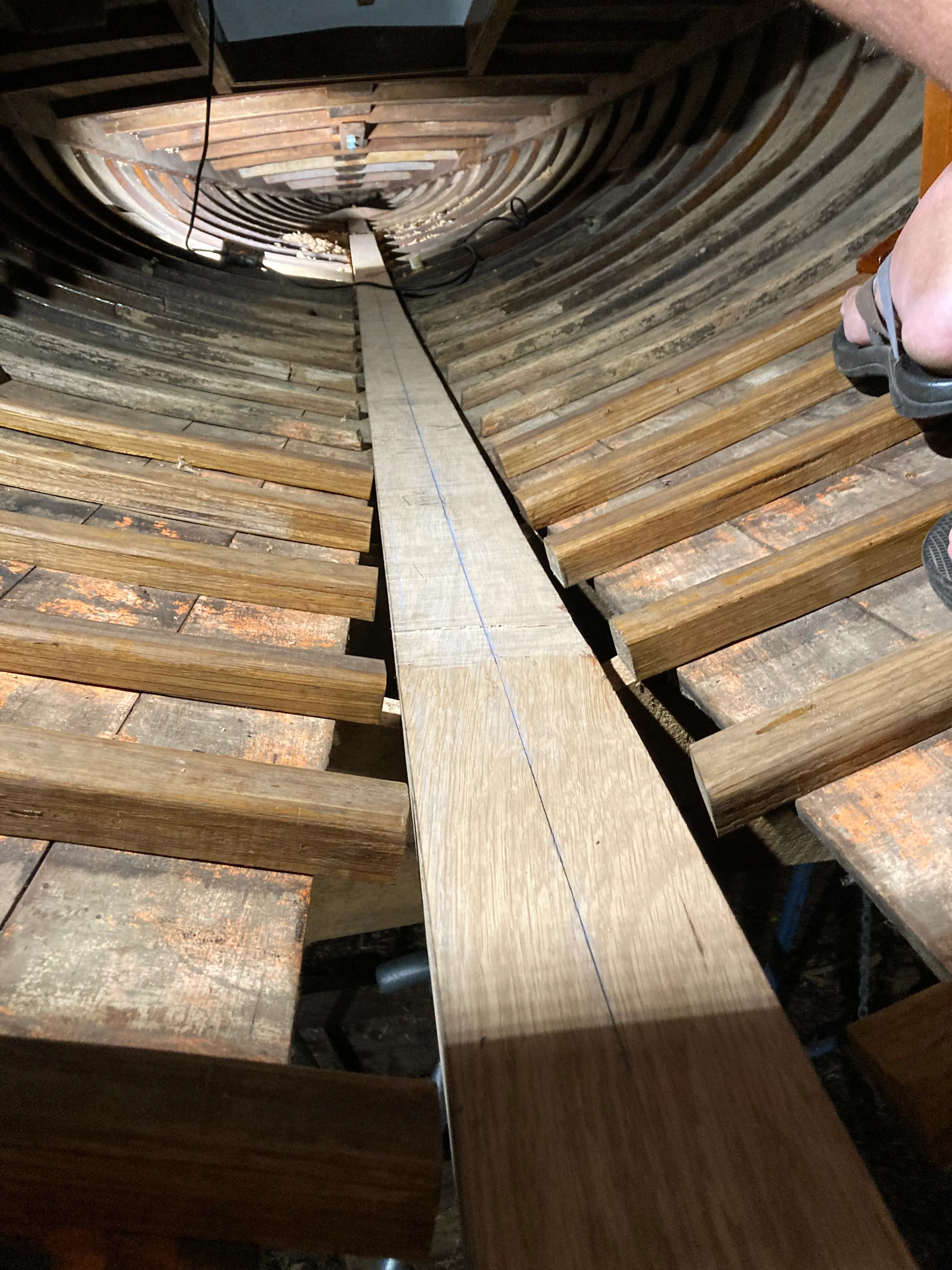
Removing the old piece without damaging it allowed us to use it as a template for cutting the new piece. This is not always possible, but it’s a great way to ensure a correct fit. We then used G-flex epoxy to laminate a blank of new oak with the right dimensions. Then we could transfer template marks to the new blank and begin removing material to reveal the correct shape.
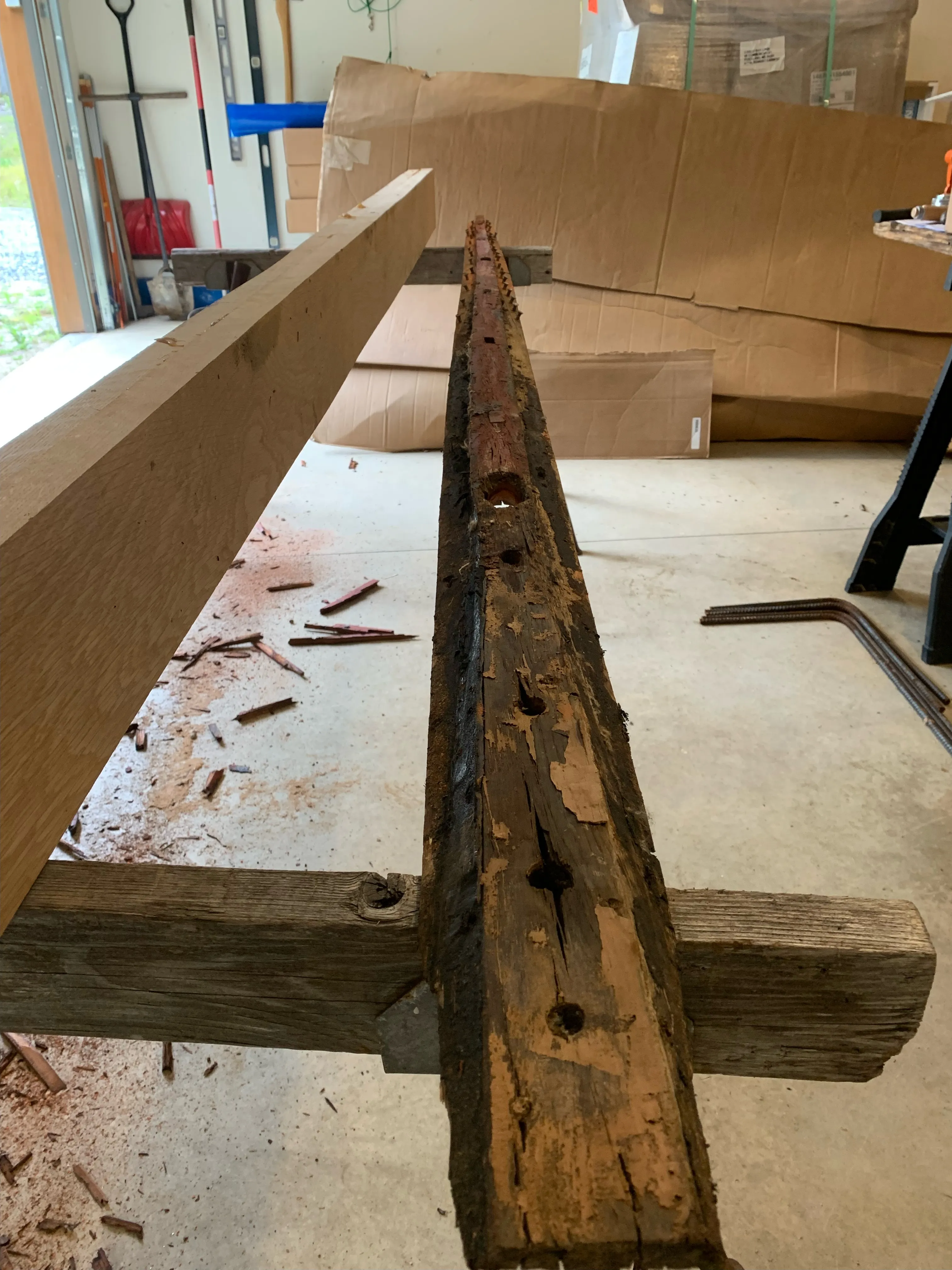
With this project, it was easy to transfer dimensions in the X dimension but more difficult in the Y dimension due to the cross-sectional shape of the piece. Our first attempt at the latter was to bore holes through the old piece and measure thicknesses (moldings in boat speak - “thickness” in which dimension? specificity is good). We would then transfer as points and batten together to create our cut line. But this was frustratingly inaccurate.
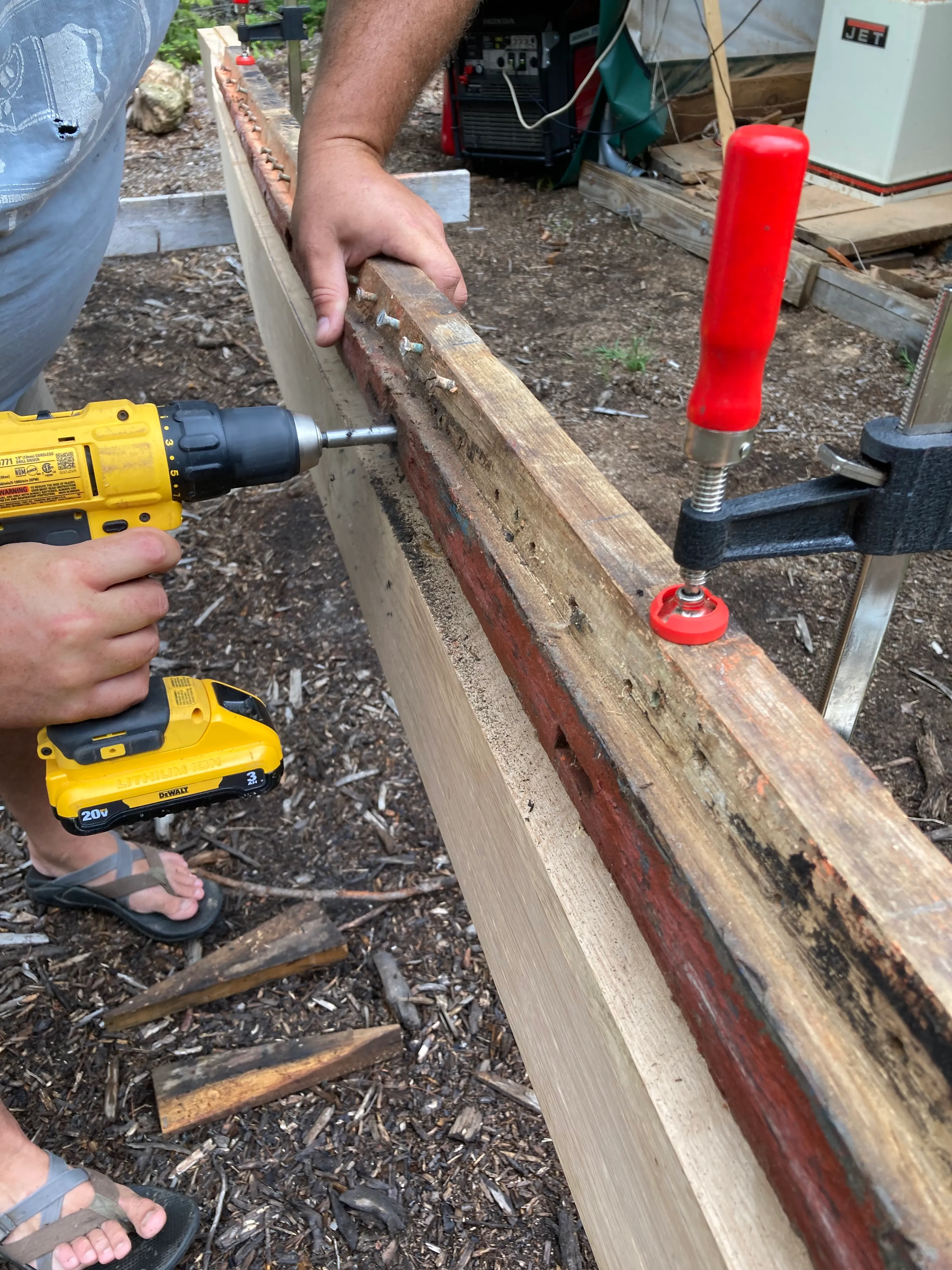
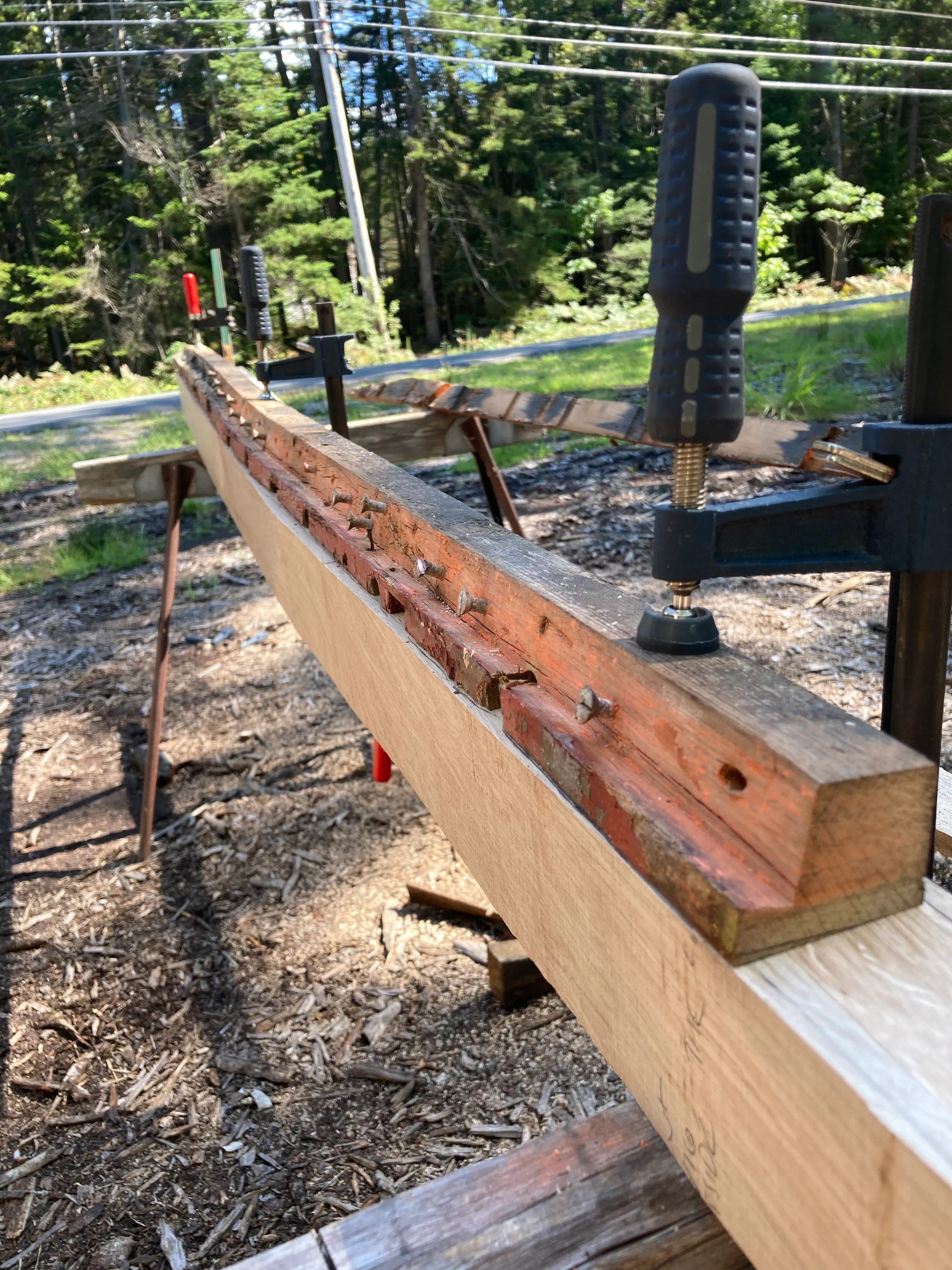
Everything got much easier once we realized we could rip the old piece in half and directly transfer the middle profile to our blank. The photo below clearly shows how we could just template the Y-dimensions directly to the blank after ripping the old piece in half.
Roughing out
After capturing the shape in the X and Y dimensions, the next step was to remove material up to the lines. Woodworking is the execution of kindergarten skills to a very high level - if your line is correct and you don’t cut beyond it, you will be fine.
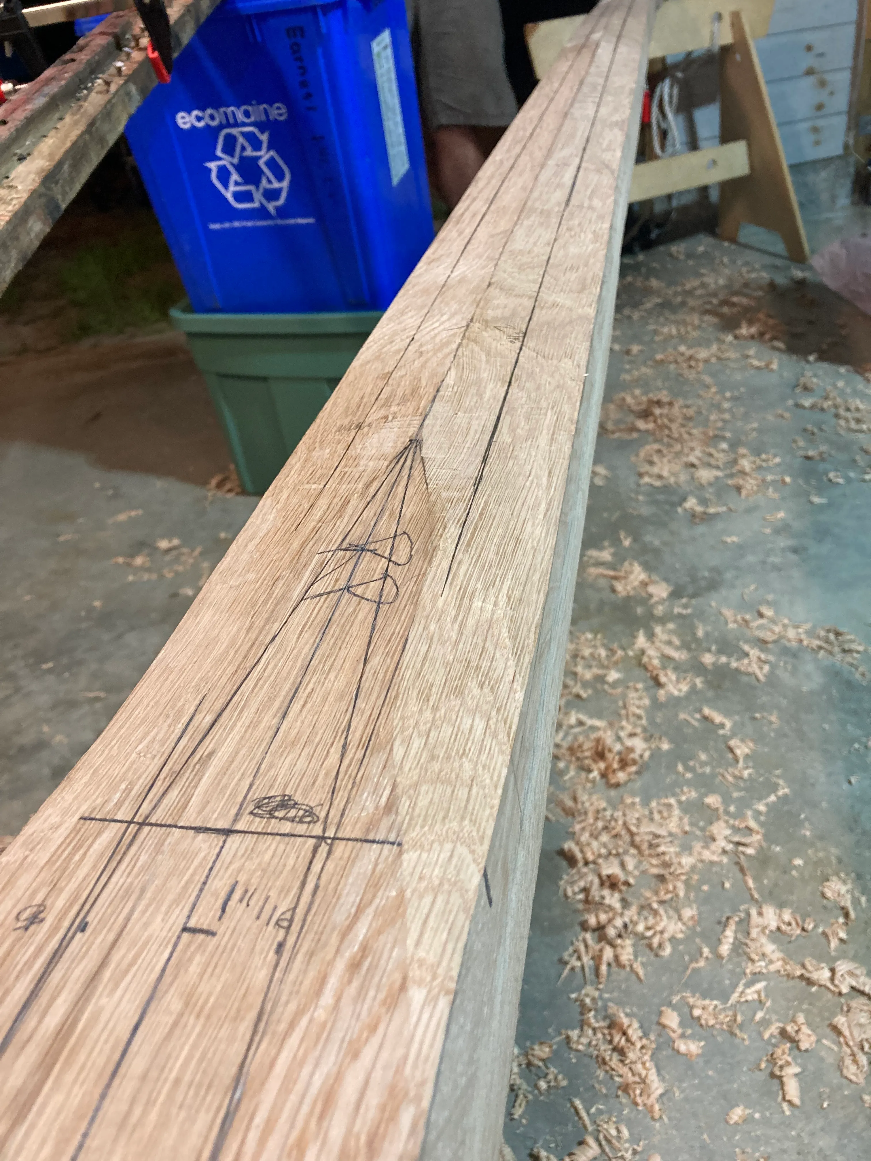
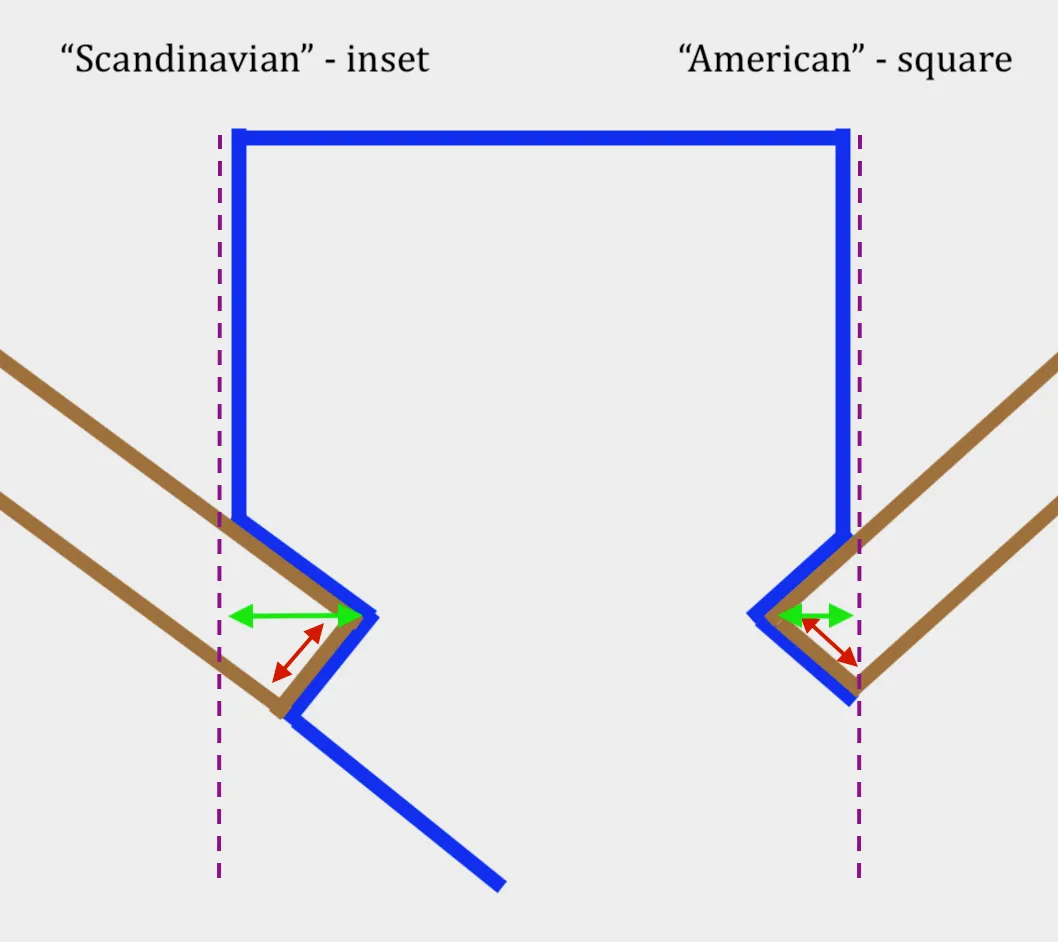
The most difficult part of the roughing out stage was to cut the rabbets. The cross section drawing below shows how a square notch cut from either side of the backbone timber will receive the planking (this image represents an MRI slice of the backbone timber right through the middle of the boat). It is far easier to cut the rabbet into the backbone before it’s installed permanently, but even then, you need to get it exactly correct - especially on a boat like this where no cotton caulking or seam compound is used (so called “tight-seamed carvel” construction).
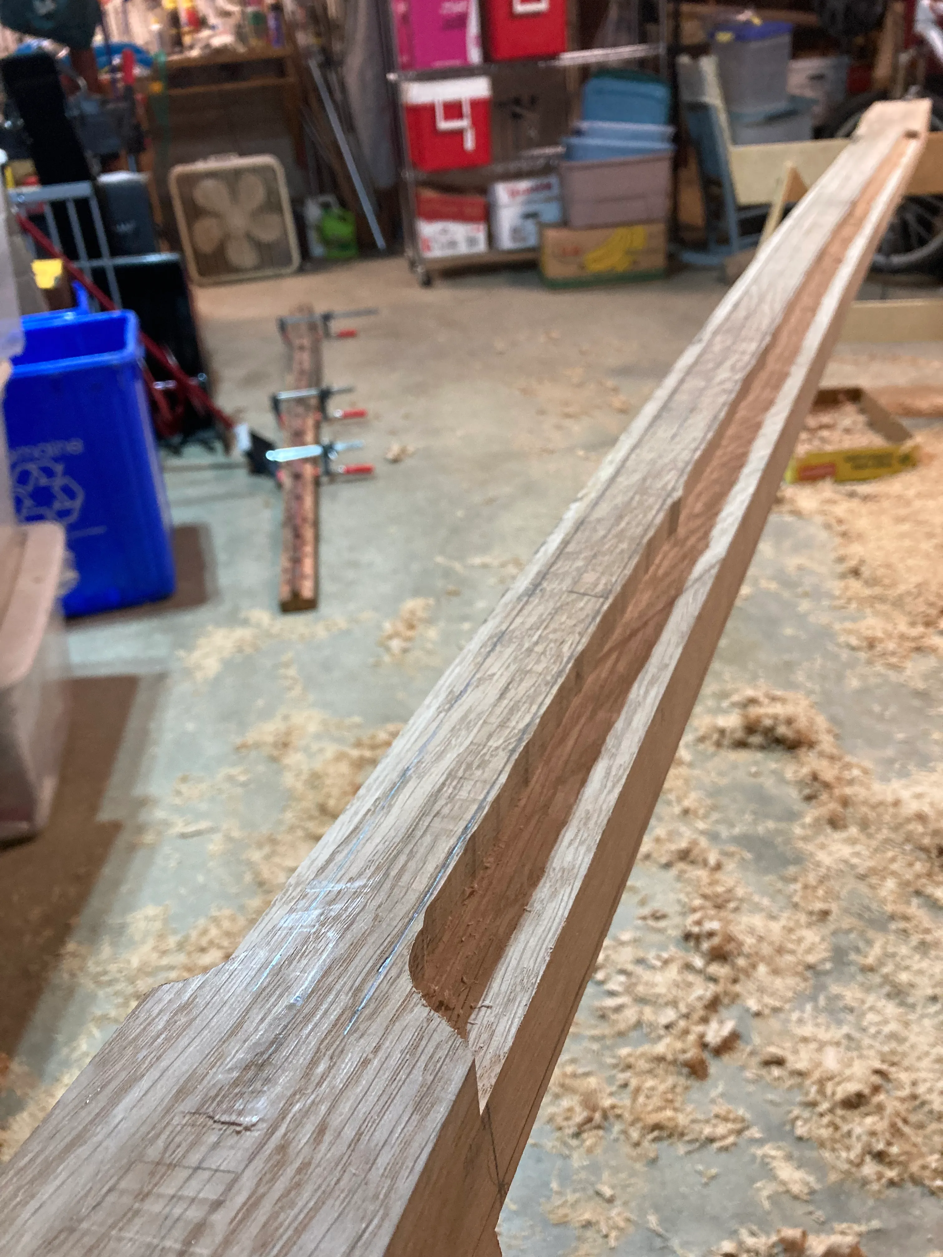
We decided to cut the bulk of the rabbets with a router, freehand to the line. This technique takes some guts and a steady hand - you go as close to the line as you dare, and try not to think about how many hours you already have invested in the piece you’re mangling at 20,000 RPM.
After the machine work, you slowly finesse the piece exactly to your line with a sharp rabbet plane.
YOLO.
Final approach to the line is done carefully with a sharp rabbet plane after the bulk of the waste was removed by the router.
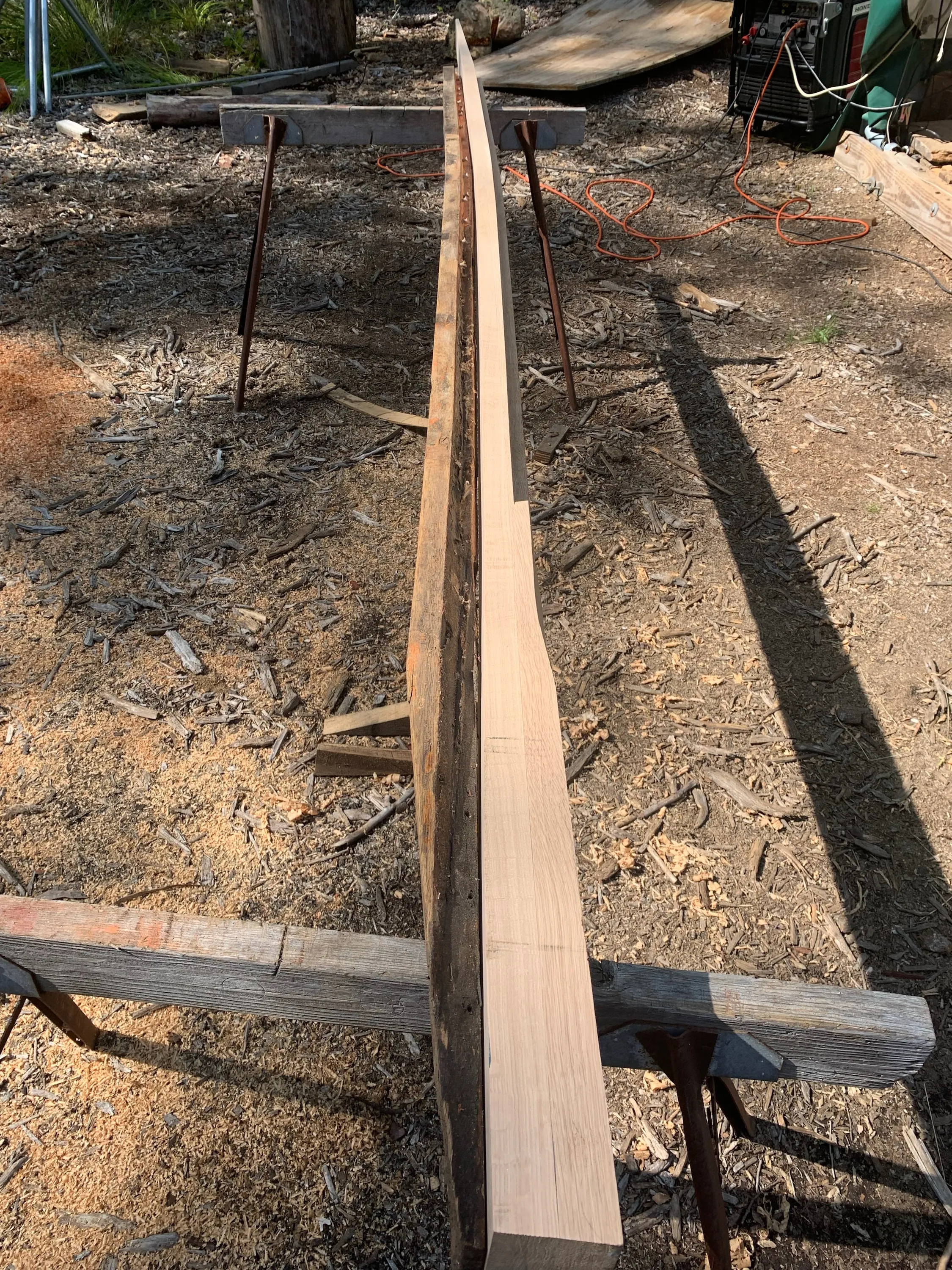
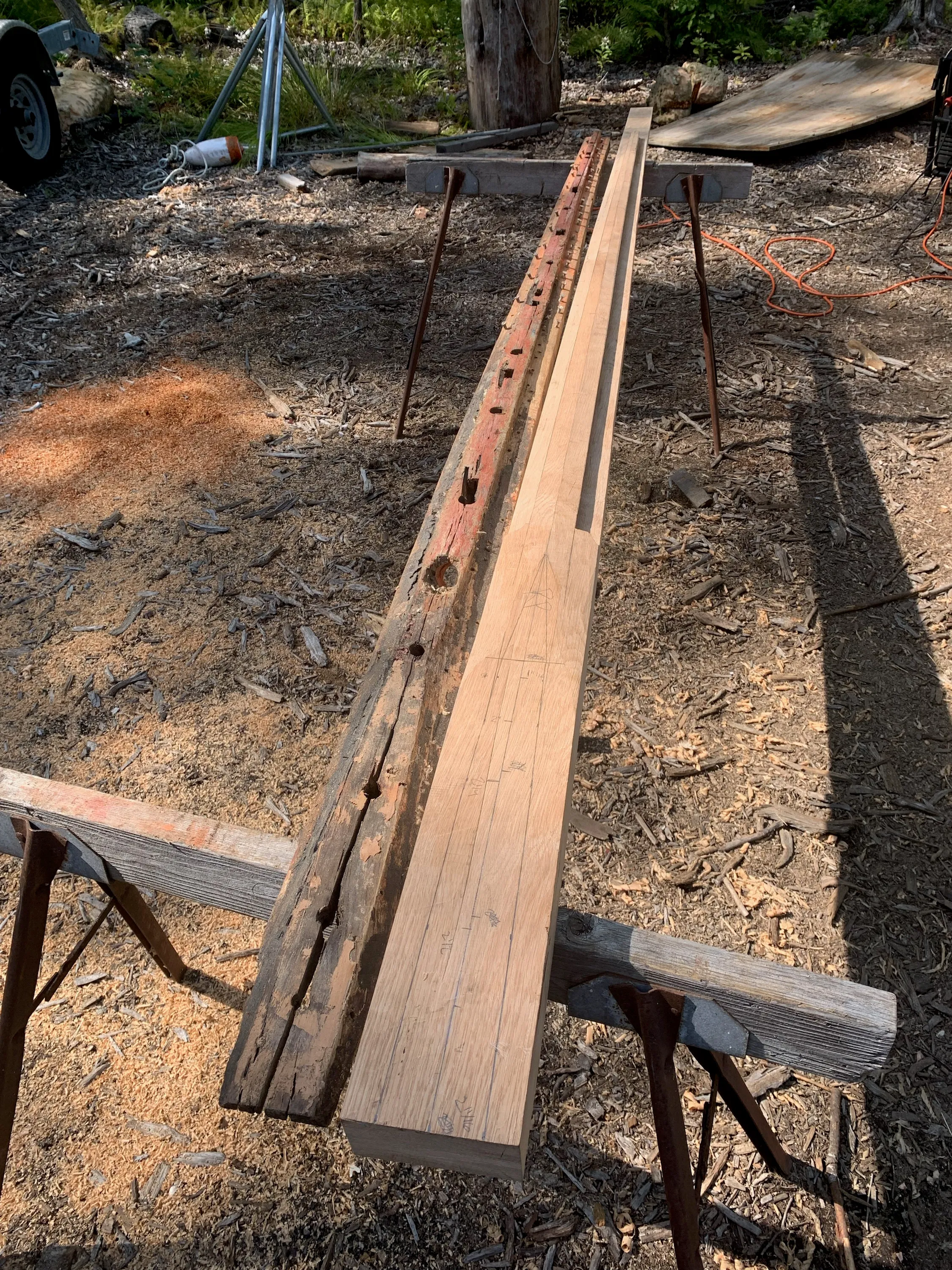
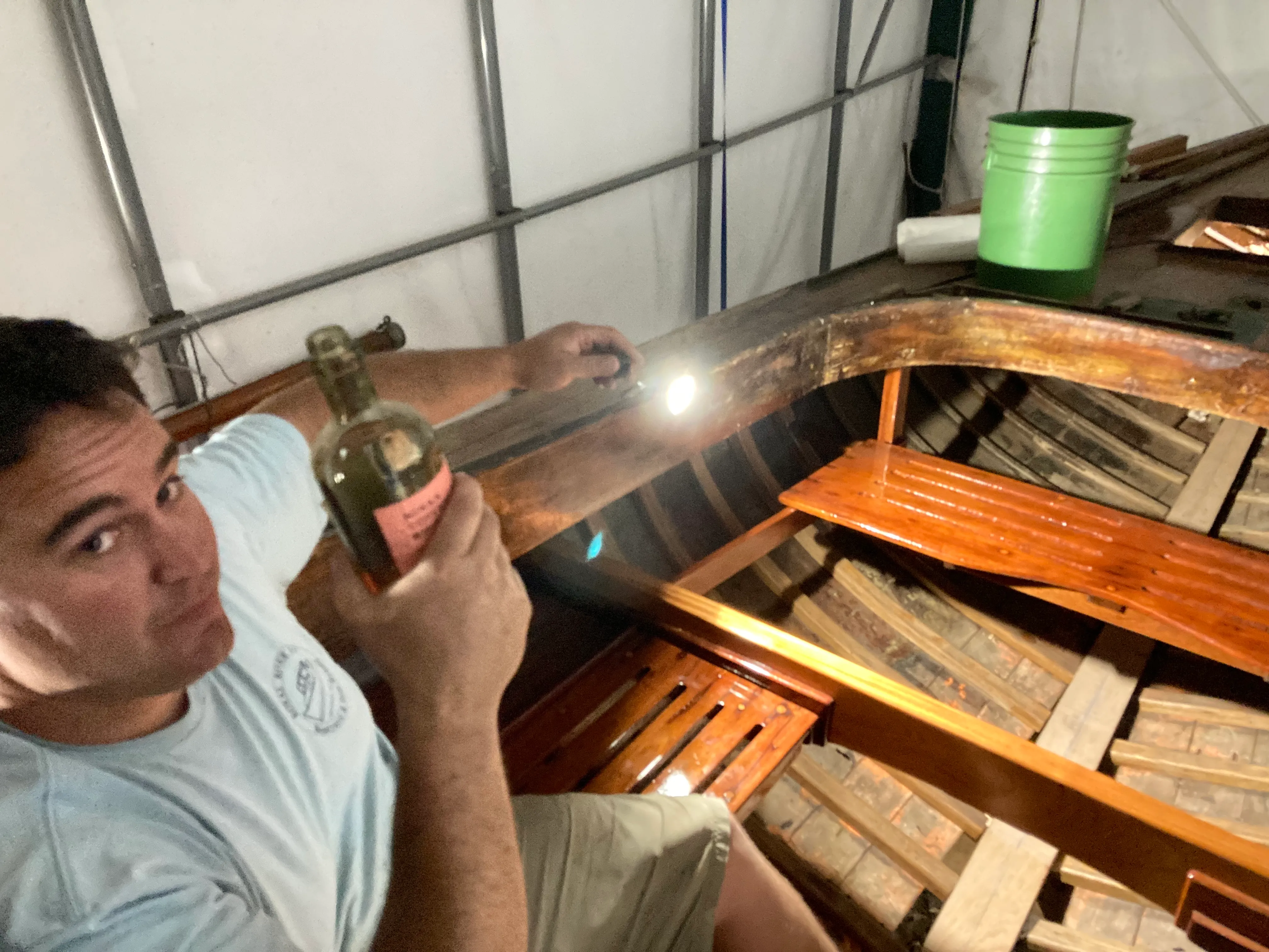
After roughing out the shape of the piece, we brought it out for a side-by-side comparison to the old aftertimber. At this point, it really feels like a major upgrade for the boat. We’re confident that we made the right decision to undertake the work.
Fitting
The most difficult part of fitting the new part was cutting the scarf joint in the aft end of the old piece. With the new blank, we could easily cut our 12:1 scarf outside of the boat using a router and a jig we made. Inside the boat there simply wasn’t room for that - we were so far back in the boat that we had maybe 12” of vertical space to work with. Not enough for even a trim router. But big enough for a human head! Barely. So, we roughed out as much as we could with the powerplaner (until we started hitting frame heels, because the powerplaner sole is too wide), then switched to a very sharp jack plane.
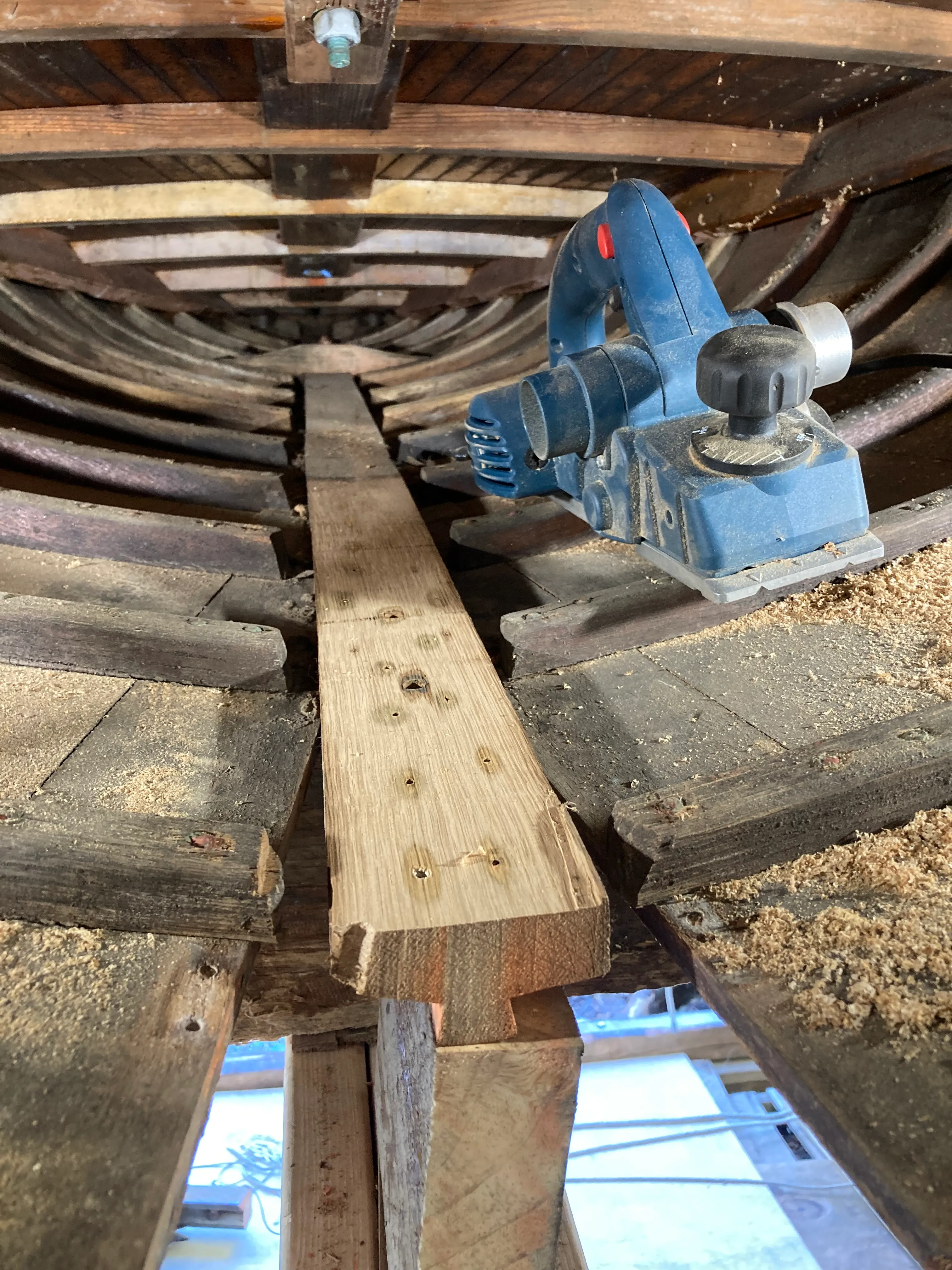
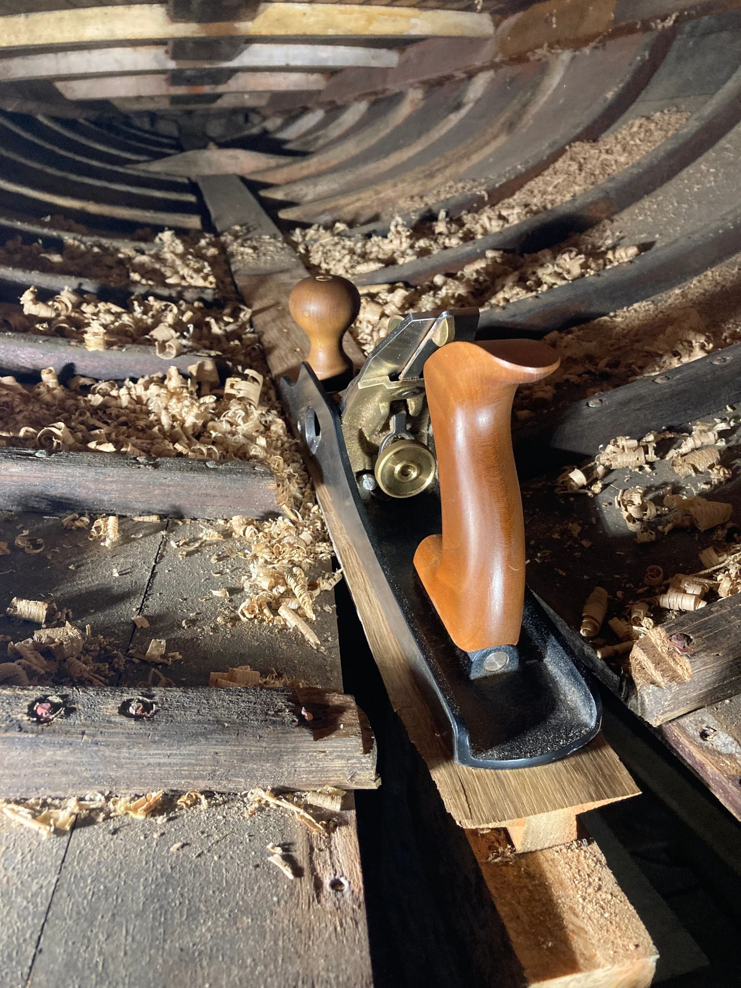
In about 3” of thickness, a 12:1 scarf runs three feet. Pushing a plane one-handed lying prone across white oak speedbumps with rivets and the occasional bolt sticking out… definitely type-2 fun. It was difficult to keep the surface perfectly flat and square to the sides, but that was the goal. Our thickened G-Flex epoxy is somewhat gap-filling but you really want to keep the mating surfaces as close to perfect as possible.
Notice how I'm planing in the incorrect direction relative to the grain - but it protects the feather edge nearest to my body. I can get away with it because my blade is very sharp. Not gonna lie, this part sucked.
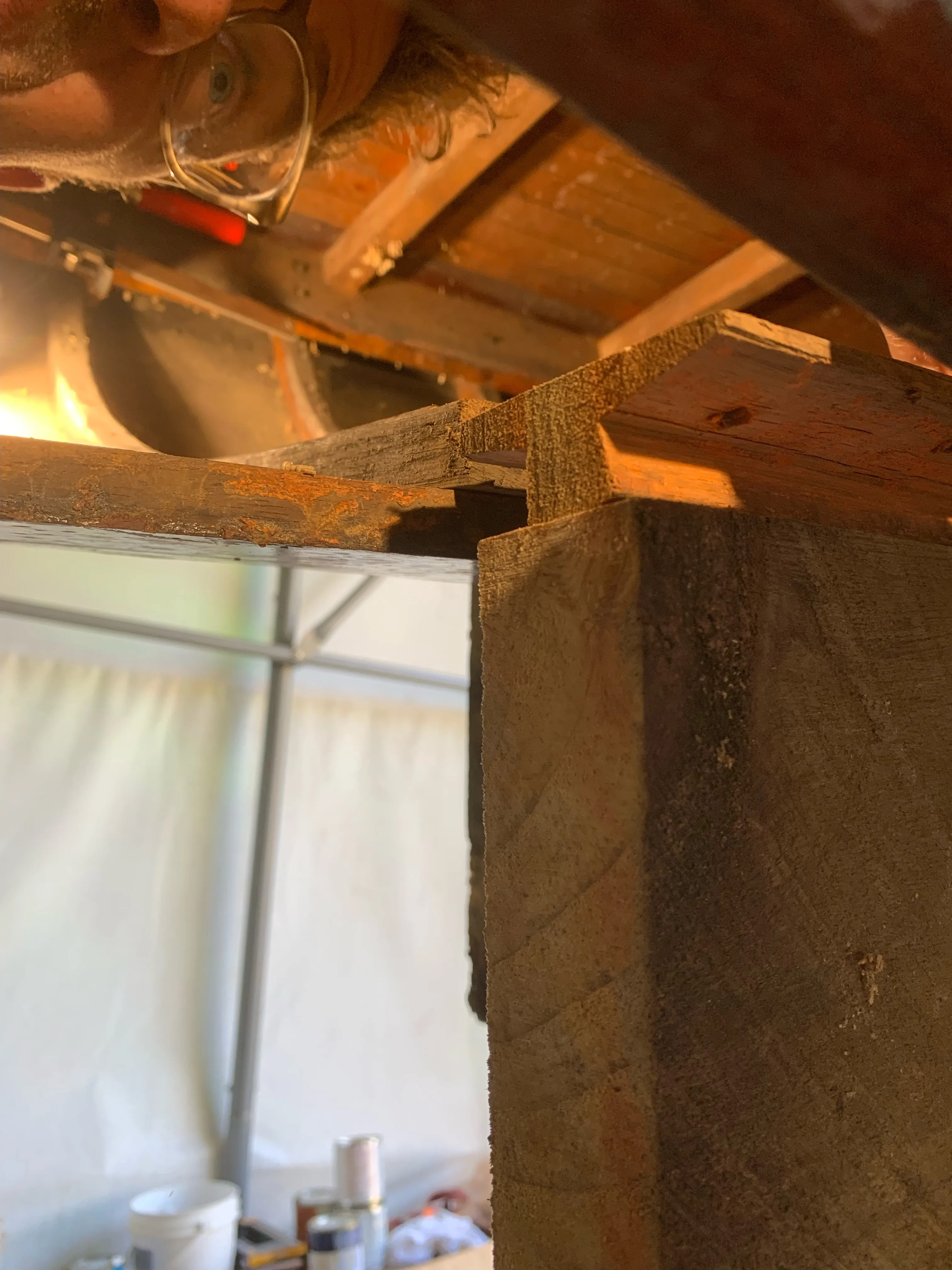
At this point, we test fit the new piece before cutting the mating scarf joint. This allowed us to precisely position the new timber fore-to-aft and mark the location of the mating side of the scarf joint. We then proceeded to cut the opposite side of the scarf using our router and jig.
Final installation
The final steps before permanently installing the new piece were to prime with red lead the section of the timber that would remain under the waterline, and varnish the rest. I think we did five coats.
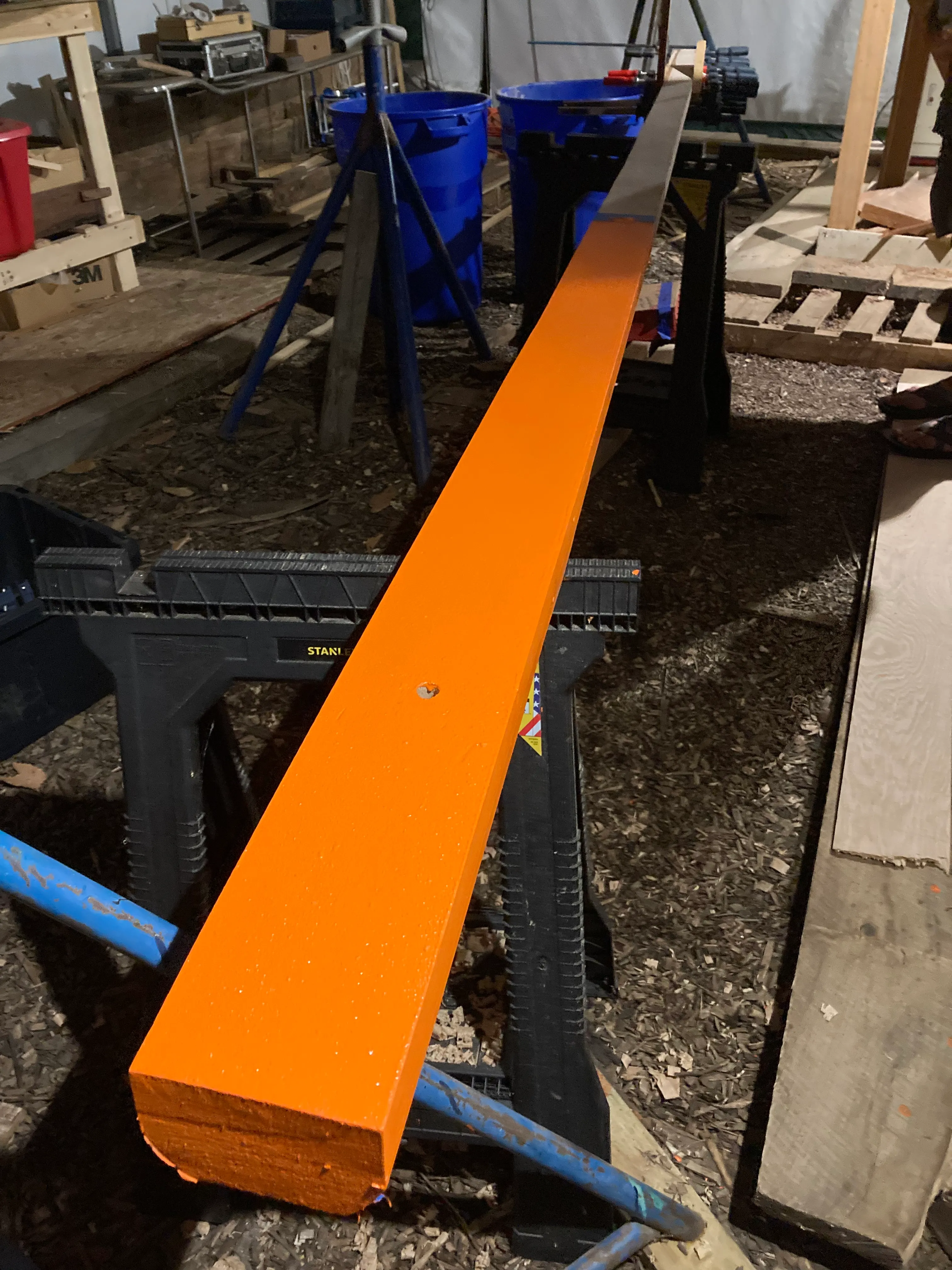
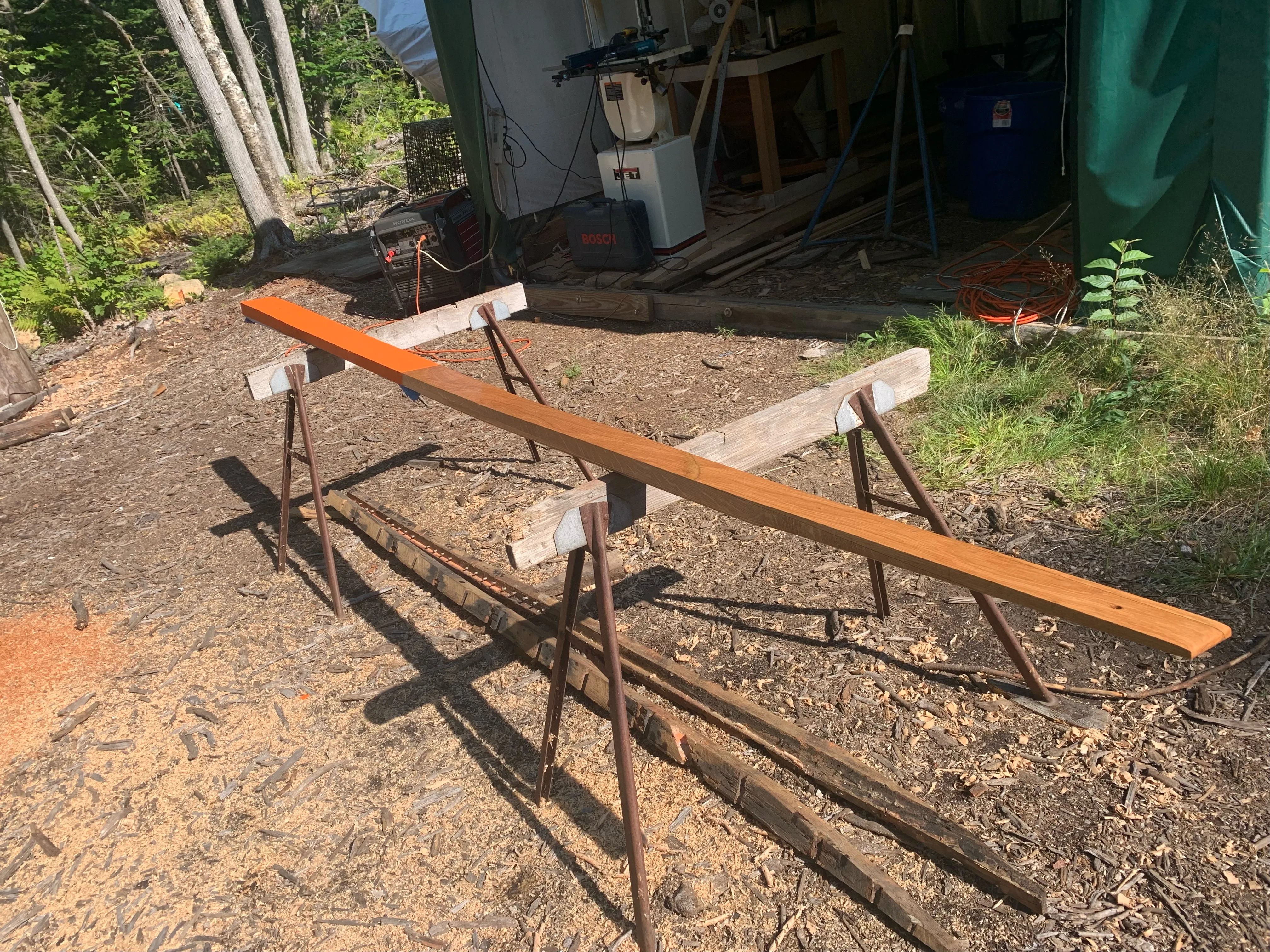
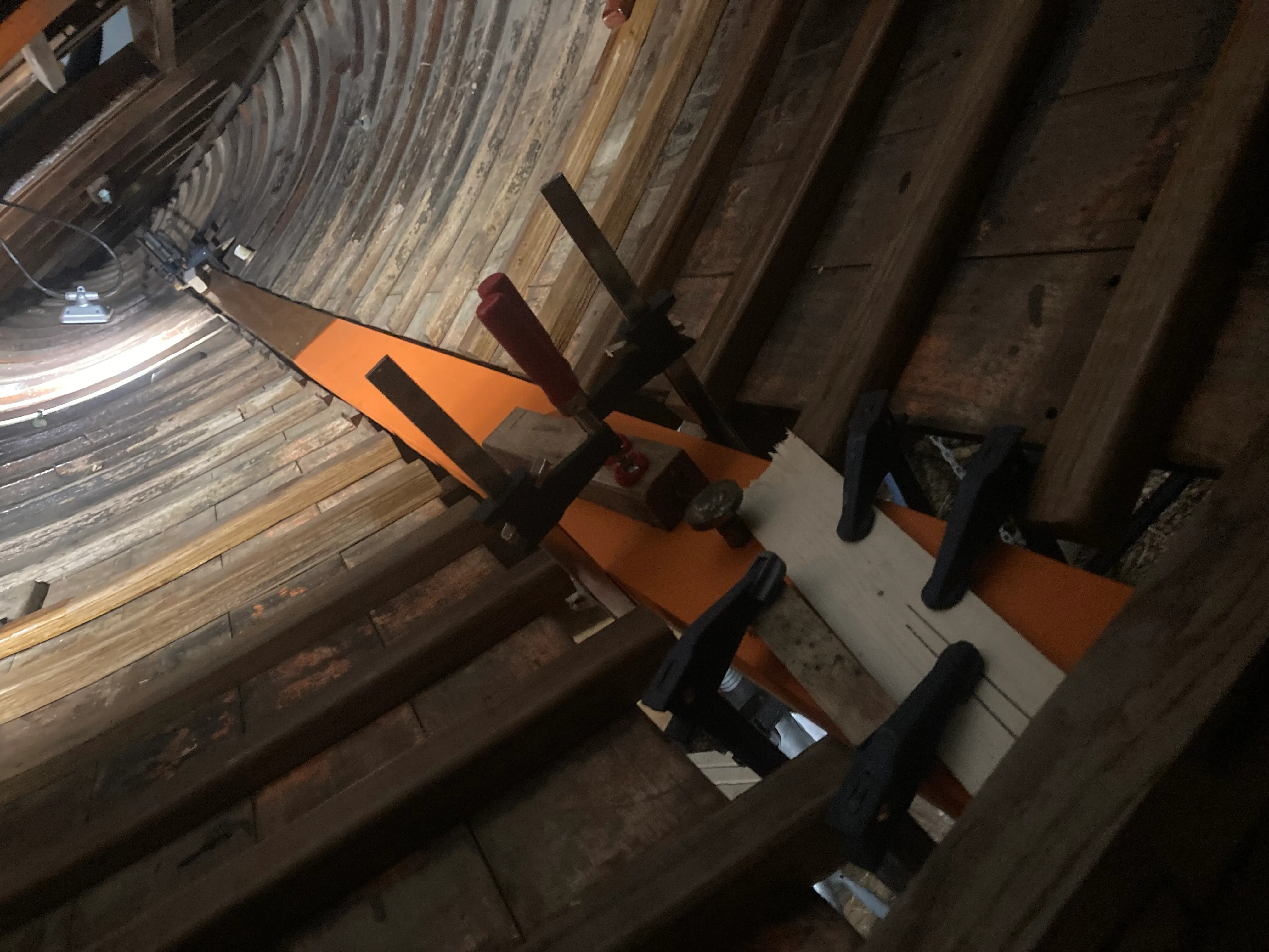
Then in she goes. We decided to epoxy the forward mating surface of the new piece to the old keel timber, rather than simply bedding it in compound and poison. The theory is that the epoxy can handle the flex and expansion, and would add torsional rigidity to this critical section of the boat. We clamped the joint together to cure, and drove some bolts home. The aft scarf was epoxied together as well.
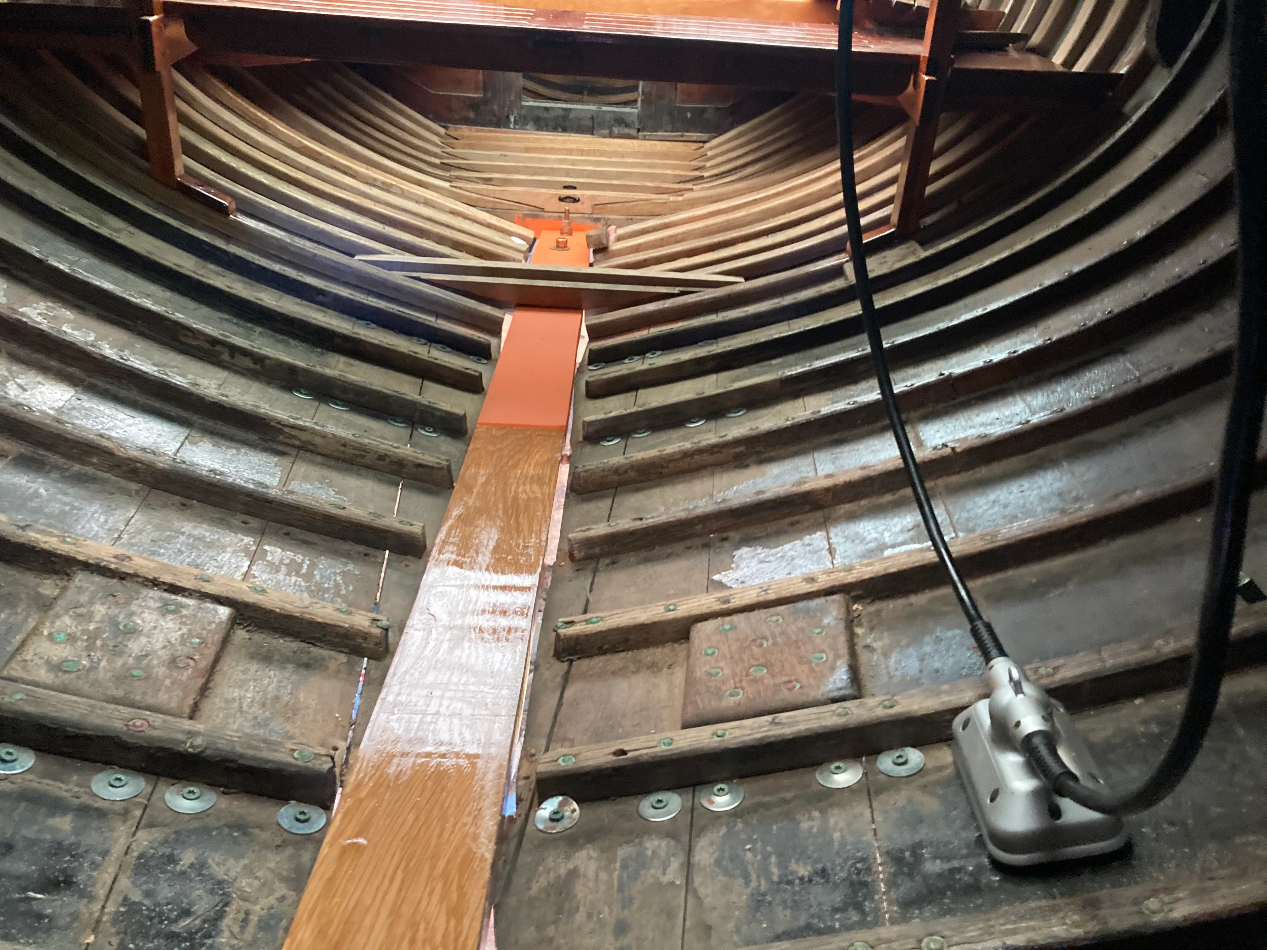
The last bit of work was to build and install a new set of floor timbers. We rebuilt these as many of the originals were compromised by iron sickness from the centerline bolts. We cut the new floors to perfectly support the bottom of the cockpit sole boards, i.e. the tops of the floors needed to be precisely coplanar. Once the new floors were installed, we could remove the external support structure and move on with our lives.
